System and method for piston cooling

A piston cooling, piston technology, applied in the direction of piston, liquid cooling, engine cooling, etc., can solve problems such as engine efficiency reduction

Active Publication Date: 2021-04-02
FORD GLOBAL TECH LLC
View PDF7 Cites 0 Cited by
  • Summary
  • Abstract
  • Description
  • Claims
  • Application Information

AI Technical Summary

Problems solved by technology

Pumps that pressurize the oil may perform extra work, resulting in reduced engine efficiency

Method used


Image

  • System and method for piston cooling
  • System and method for piston cooling
  • System and method for piston cooling

Examples


Embodiment Construction

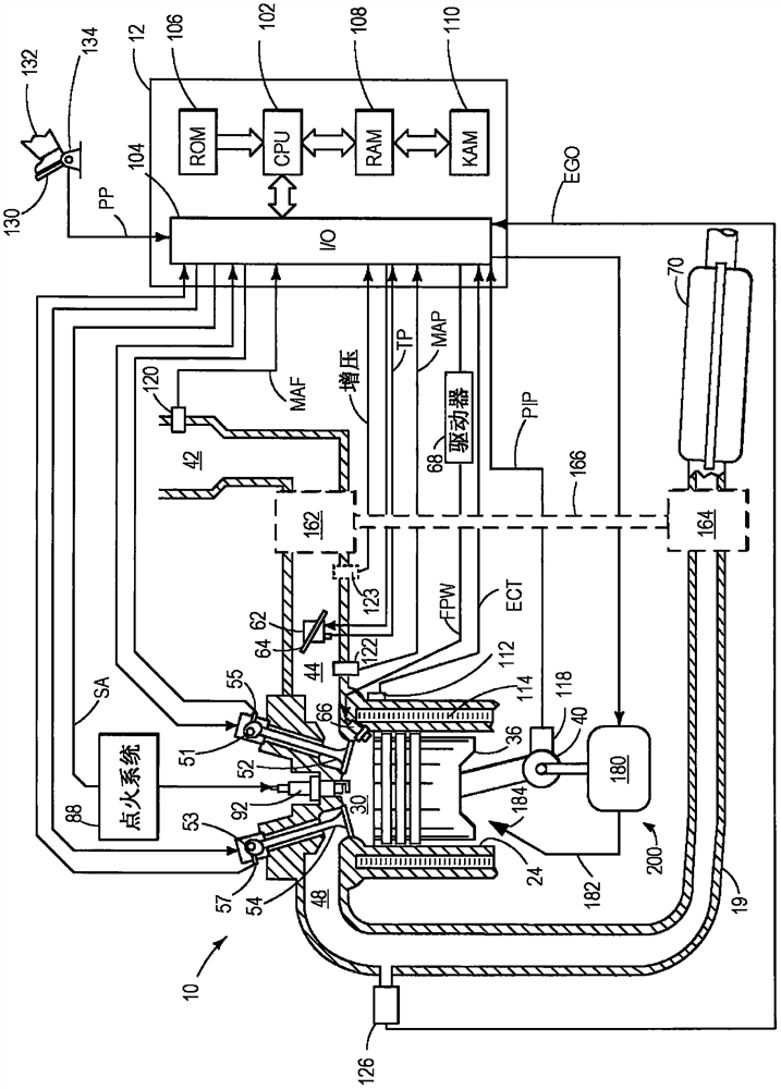
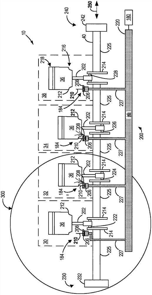
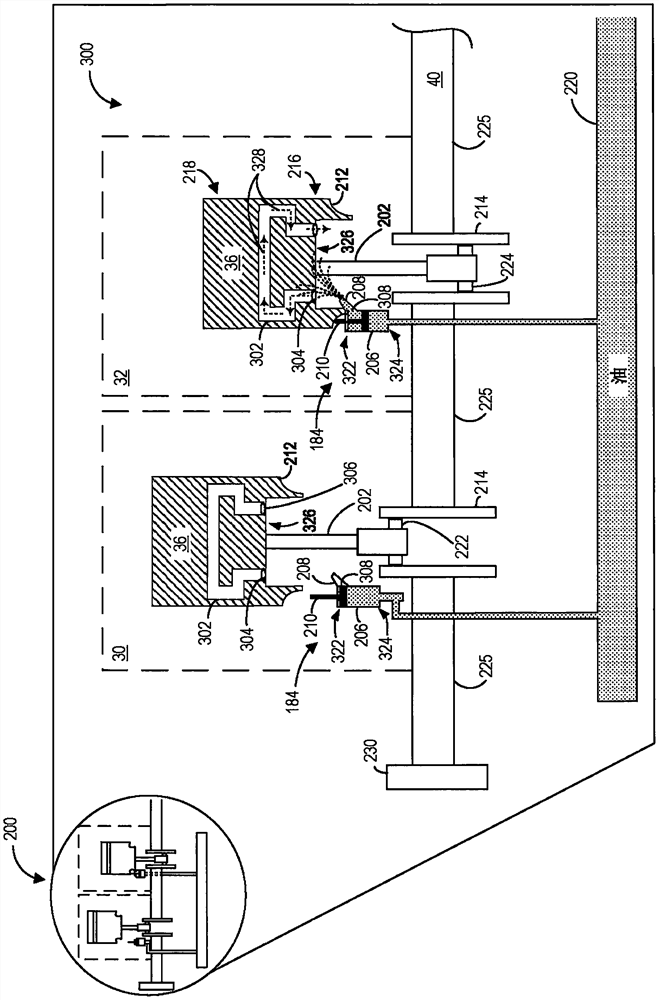
[0016] The following description refers to cooling in the engine (for example, in figure 1 Systems and methods for pistons in the engine shown in ). as in figure 2 As shown in , the engine includes a plurality of pistons and a crankshaft, each piston reciprocating within a cylinder of the engine; and the crankshaft is lubricated and cooled by a lubrication system having an oil pump, oil passages, and a plurality of piston cooling assemblies. Each of the plurality of pistons may receive cooling oil via an associated piston cooling assembly. Such as image 3 As shown, the piston cooling assembly may include a poppet valve, a valve body, and a nozzle. The piston cooling assembly may inject oil onto the associated piston when the associated piston reaches a bottom dead center (BDC) position. Further, the supply may be terminated as the associated piston travels towards top dead center (TDC). Therefore, the oil supply may only be repeatedly activated during a portion of each ...


PUM


Abstract

The present application discloses systems and methods for piston cooling. The present application provides methods and systems for supplying cooling oil to pistons of engine cylinders. In one example, the method may include repeatedly activating the oil supply only during a portion of the cylinder cycle that is synchronized with reciprocating motion of the piston. In particular, the supply of cooling oil may be initiated by displacing a poppet valve provided in the piston cooling assembly via the reciprocating movement of the piston.

Description

technical field [0001] The present disclosure generally relates to methods and systems for piston cooling. Background technique [0002] The thermal load on the pistons within the engine's cylinders increases in response to the demand for higher power output and lower emissions. However, the increased thermal load on the piston may cause problems such as engine seizure and engine degradation. Also, designing the piston to avoid such degradation may involve more costly materials and manufacturing methods, or sacrifice other desirable properties. [0003] The lubrication system may be used to cool various engine components during a dynamic range of engine operating conditions. For example, the piston may be cooled by piston cooling jets, in which oil is sprayed on the bottom surface of the piston. Chimonides et al. in US Pat. No. 6,298,810 describe an example piston cooling assembly in which oil injectors are located on the engine block to supply oil to the bottom surface o...

Claims


Application Information

Patent Timeline
Patent Type & Authority Patents(China)
IPC IPC(8): F01P3/08
CPCF01P3/08F01M1/14F01M1/16F01M1/08F02F3/22
Inventor T·G·里昂
Owner FORD GLOBAL TECH LLC
Why Eureka
Try Eureka