Decorative cover mounting structure of range hood

A technology of a range hood and an installation structure, which is applied in the field of range hoods, can solve the problems of cracking of tiles, troublesome installation, inability to install a decorative cover, etc., and achieves the effects of low installation cost and convenient adjustment.

Active Publication Date: 2016-10-26
NINGBO FOTILE KITCHEN WARE CO LTD
View PDF6 Cites 20 Cited by
  • Summary
  • Abstract
  • Description
  • Claims
  • Application Information

AI Technical Summary

Problems solved by technology

During installation, workers generally need to drill four holes on the wall to install expansion screws. Not only is the installation more troublesome, but also because the installation space of the decorative cover is relatively small, the distance between the decorative cover hook hole and the lower hook hole of the whole machine is relatively close. Therefore, it is easy to cause

Method used


Image

  • Decorative cover mounting structure of range hood
  • Decorative cover mounting structure of range hood
  • Decorative cover mounting structure of range hood

Examples


Embodiment 1

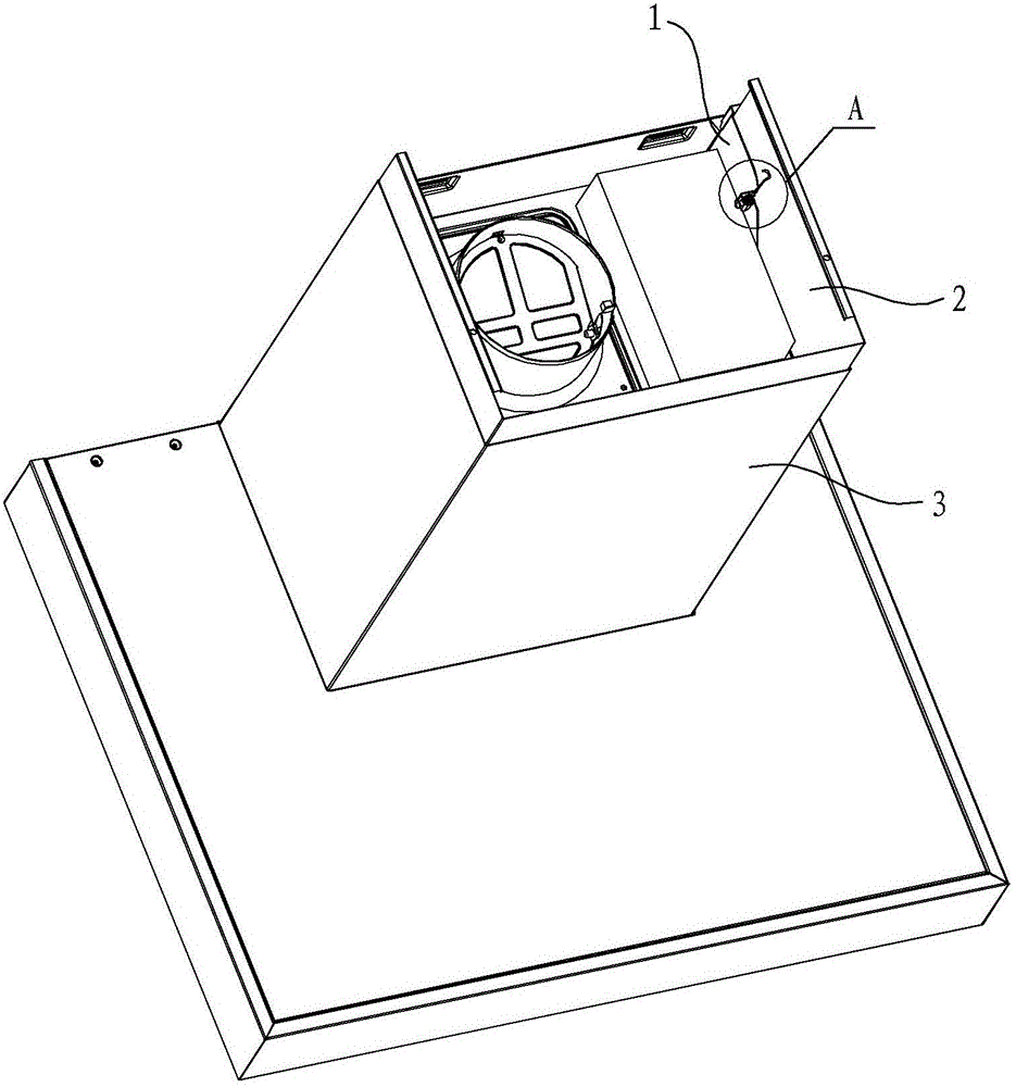
[0028] Such as Figure 1 to Figure 4 As shown, the decorative cover installation structure of the range hood in this embodiment includes a fan frame 1 and a decorative cover 2, the fan frame 1 is fixed inside the fan cover 3, and the decorative cover 2 is limited between the fan cover 3 and the fan cover. In the interlayer between the frames 1 and can move up and down relative to the fan cover 3, the outer wall of the decorative cover 2 is offset against the inner wall of the fan cover 3, that is, the fan cover 3 constitutes a limit plate that prevents the decorative cover 2 from moving to the outside. A torsion spring installation bracket is formed on the left and right side walls of the fan frame 1, and a torsion spring and a torsion adjustment member are installed on the torsion spring installation bracket. The torque regulating member can directly act on the second force application end of the torsion spring, and further adjust the pressing force of the first force applica...

Embodiment 2

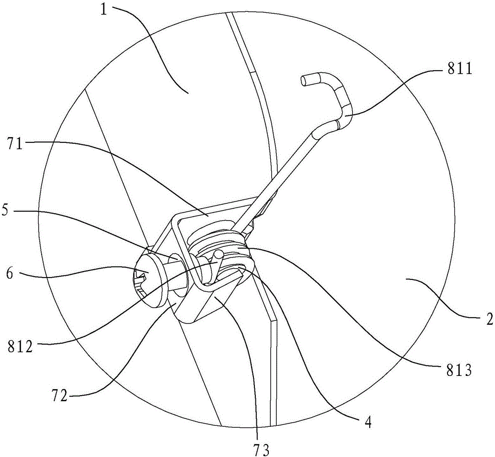
[0034] Such as Figure 5 to Figure 8 As shown, the torsion spring mounting bracket in this embodiment is formed with two installation shafts 4 arranged sequentially along the folding direction of the first flange 71 on the first flange 71, and the second torsion spring 82 includes two mounting shafts. The winding unit 823 on the corresponding installation shaft 4 , the outer ends of the two winding units 823 respectively form the first force application end 821 and the second force application end 822 of the second torsion spring. The rest of the structure in this embodiment is the same as that in Embodiment 1, and will not be further described here.

Embodiment 3

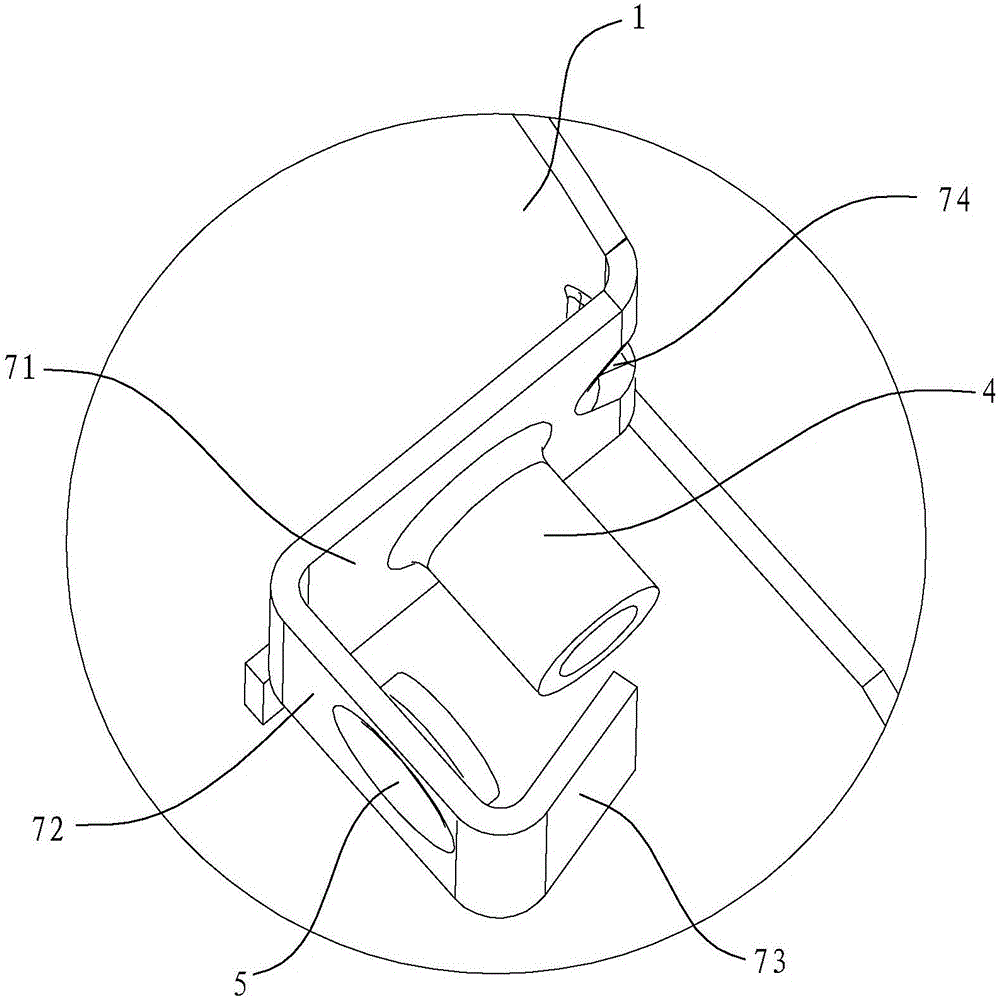
[0036] Such as Figure 9 to Figure 12As shown, the torsion spring mounting bracket in this embodiment includes a first bent piece 91 and a second bent piece 92 that are perpendicular to each other. Both the left side wall and the right side wall of the fan frame 1 are bent inward to form a first bent piece 91, and one side of the first bent piece 91 is provided with a mounting shaft 4, and a threaded inner hole is provided on the mounting shaft 4 , the other side of the first bending piece 91 is provided with a limit screw 10, and the limit screw 10 can be screwed into the threaded inner hole of the installation shaft 4. A mounting hole 5 is opened on the second bending piece 92 . The torsion spring in this embodiment is the third torsion spring 83, which includes two winding units 833 respectively installed on the installation shaft 4 and the limit screw 10, the outer ends of the two winding units 833 A first force application end 831 of the third torsion spring is formed, ...


PUM


Abstract

The invention discloses a decorative cover mounting structure of a range hood. The structure comprises a fan frame and a decorative cover; the decorative cover can move up and down corresponding to a fan cover; and the outer side wall of the decorative cover is butted against a limiting plate positioned out of the decorative cover. The structure is characterized in that torsion spring mounting brackets are arranged on two opposite side walls of the fan frame; torsion springs and torsion adjusting pieces are mounted on the torsion spring mounting brackets; first force applying ends of the torsion springs are butted against the corresponding inner side walls of the decorative cover; and the torsion adjusting pieces can be directly acted on second force applying ends of the torsion springs to adjust the pressing force of the first force applying ends of the torsion springs on the inner side wall of the decorative cover. The decorative cover mounting structure of the range hood has the following advantages: the decorative cover mounting structure of the range hood can adjust the pressing force of the first force applying ends of the torsion springs to the decorative cover through adjusting the acting force of the torsion adjusting pieces to the second force applying ends of the torsion springs, so that the decorative cover can be adjusted in any height without slipping, the adjustment is more convenient and flexible, the mounting cost is lower, and the structure can adapt to mount decorative covers with different weights.

Description

technical field [0001] The invention relates to a range hood, in particular to a decorative cover installation structure of the range hood. Background technique [0002] The decorative cover of the range hood is used to cover the air outlet cover and the air duct on the top of the range hood, which plays an aesthetic and decorative role. The decorative cover can usually be drawn out from the top of the fan cover of the range hood, and can be adjusted according to the user's house. height adjustment. The traditional range hood decorative cover is supported by a screw-fixed hook. When installing, first fix the decorative cover hook on the wall with expansion screws, then push the decorative cover flat into the groove of the front cantilever of the decorative cover hook, and finally install the fan cover . During installation, workers generally need to drill four holes on the wall to install expansion screws. Not only is the installation more troublesome, but also because the...

Claims


Application Information

Patent Timeline
IPC IPC(8): F24C15/20
CPCF24C15/2071
Inventor 何立博茅忠群诸永定申志贤
Owner NINGBO FOTILE KITCHEN WARE CO LTD
Why Eureka
Try Eureka