High-speed train axle box bearing test bench based on vibration rolling

A technology for axle box bearings and high-speed trains, which is used in mechanical bearing testing, mechanical component testing, and machine/structural component testing.

Inactive Publication Date: 2016-10-26
SOUTHWEST JIAOTONG UNIV
View PDF5 Cites 7 Cited by
  • Summary
  • Abstract
  • Description
  • Claims
  • Application Information

AI Technical Summary

Problems solved by technology

(3) The track is not smooth, such as wave grinding, triangular pit
At present, the existing railway bearing test research is mainly the

Method used


Image

  • High-speed train axle box bearing test bench based on vibration rolling

Examples


Embodiment Construction

[0014] The present invention will be described in detail below in conjunction with specific embodiments.

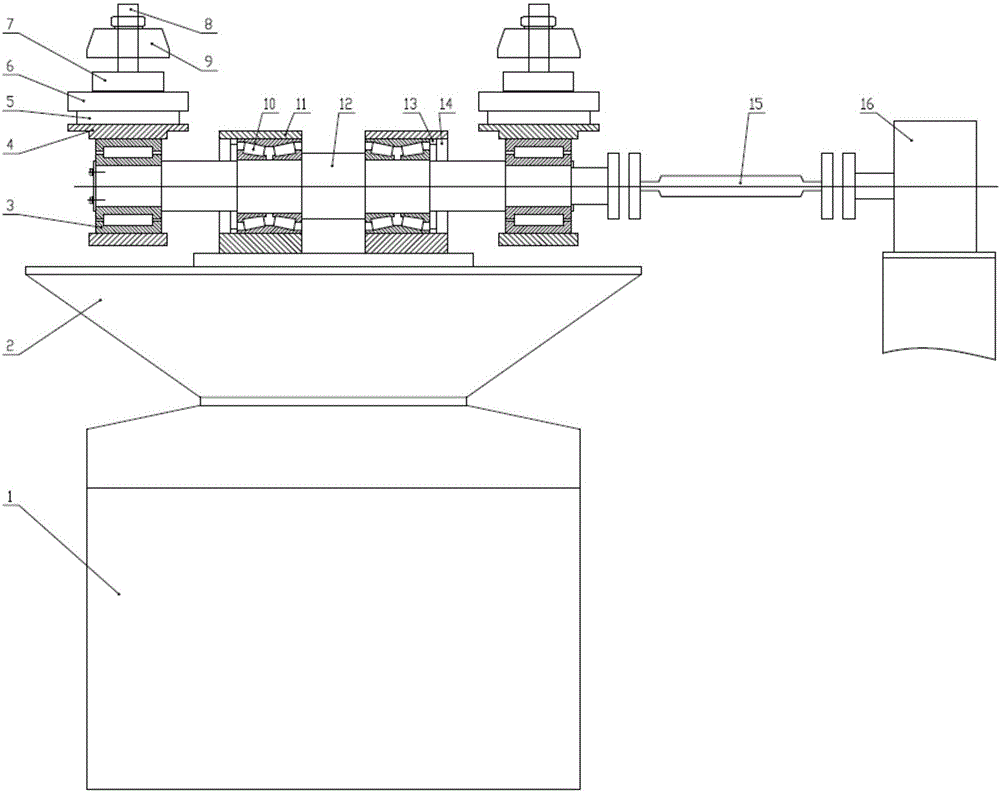
[0015] Such as figure 1 Shown: a high-speed train axle box bearing test rig based on rolling vibration, characterized in that the test rig includes an electromagnetic excitation table (1), an extended table (2), a vertical force loading component, a tested component, and a main shaft (12), universal coupling (15) and motor (16);

[0016] The electromagnetic excitation table (1) is located at the lower part of the test bench, the upper part of the electromagnetic excitation table (1) is connected with the lower part of the extended table (2), and there are two vertical force loading parts located on the main shaft (12 ), the two ends of the tested component are located in the middle of the main shaft (12), and one end of the main shaft (12) is connected with the motor (16) by a universal coupling (15);

[0017] The vertical force loading part is composed of a supporting ...


PUM


Abstract

The invention discloses a high-speed train axle box bearing test bench based on vibration rolling, which is characterized by comprising an electromagnetic vibration table (1), an extended table (2), a vertical force loading unit, a tested part, a spindle (12), a universal coupling (15) and a motor (16). The test bench can be used for axle box bearing test for a high-speed train at up to 350km/h.

Description

technical field [0001] The invention relates to a high-speed train axle box bearing test bench based on rolling vibration. Background technique [0002] Axlebox bearings are key components of the running part of high-speed trains. Their operating conditions, dynamic performance and service life have a vital impact on the safe, stable and efficient operation of trains. From the current actual operation of high-speed trains, it can be seen that various failures of axle box bearings have occurred frequently, and they have failed prematurely before reaching the rated life. [0003] Due to the particularity of the operating environment of high-speed trains, the axle box bearings are in service under very harsh and complex working conditions: (1) The operating interval of intercity trains (such as Chengdu-Chongqing, Yangtze River Delta) is short, and the vehicle starts, accelerates, decelerates, And braking is frequent, which means that the dynamic load range of the axlebox beari...

Claims


Application Information

Patent Timeline
IPC IPC(8): G01M13/04
CPCG01M13/04G01M13/045
Inventor 李永健张卫华熊庆盖利森李杨朱少成陆天炜梅桂明张文颢
Owner SOUTHWEST JIAOTONG UNIV
Why Eureka
Try Eureka