
Vibration test device and test method for airplane panel connecting piece
A technology for vibration testing and connecting parts, applied in the field of standard parts testing, can solve the problems of cumbersome vibration direction conversion, inability to simulate the actual working environment of constant force load, etc., and achieve the effects of great practical value, easy popularization and application, and high test efficiency.
- Summary
- Abstract
- Description
- Claims
- Application Information
AI Technical Summary
Problems solved by technology
Method used
Image

Examples
Embodiment Construction
[0045] Hereinafter, embodiments of the present invention will be described with reference to the drawings.
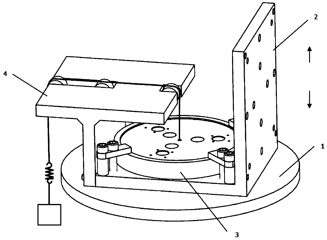
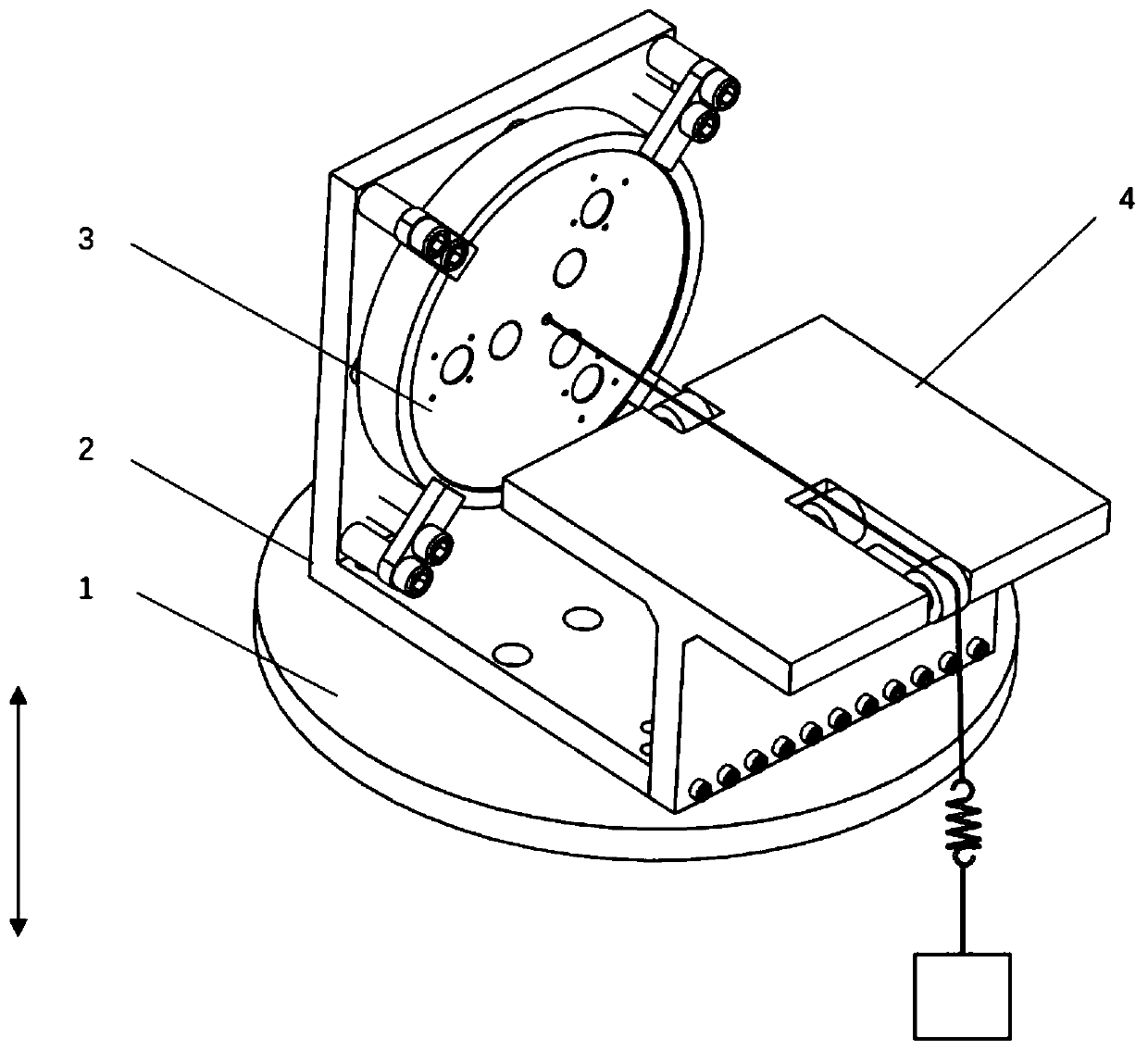
[0046] Such as figure 1 , figure 2 ,and Figure 6 A vibration test device for aircraft panel connectors is shown, which includes a vibration table 1 , an adapter unit 2 , a panel unit 3 and a loading unit 4 .
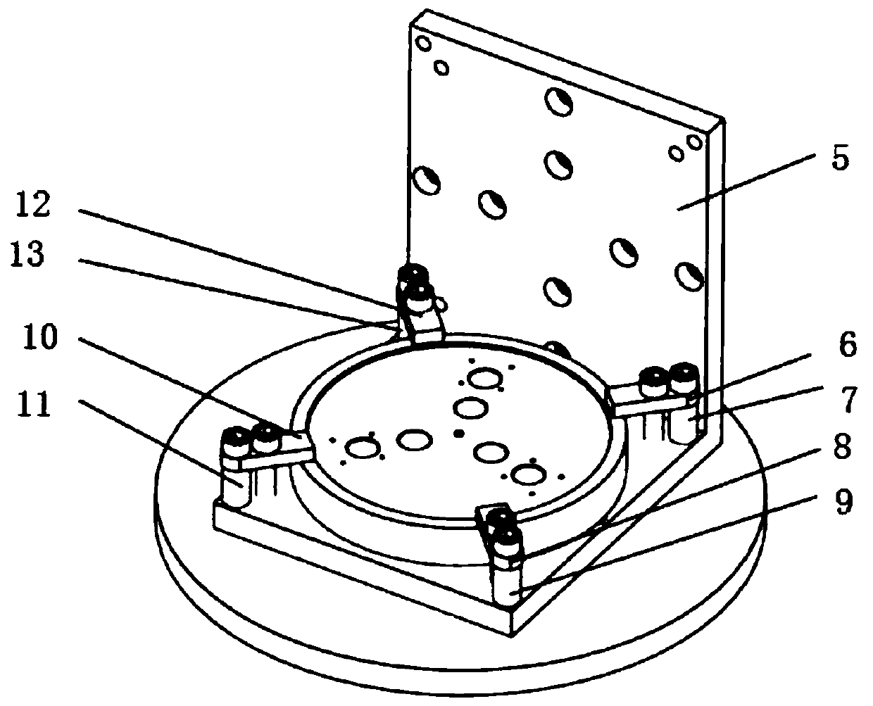
[0047] Such as image 3The shown adapter unit 2 includes an adapter plate 5 , a first pressure plate 6 , a first sleeve 7 , a second pressure plate 8 , a second sleeve 9 , a third pressure plate 10 , a third sleeve 11 , and a fourth pressure plate 12 And the fourth sleeve 13, the first pressure plate 6 is fixed on the threaded hole on the adapter plate 5 by bolts and the first sleeve 7, and the second pressure plate 8 is fixed on the adapter plate 5 by bolts and the second sleeve 9 The third pressure plate 10 is fixed on the threaded hole on the adapter plate 5 through bolts and the third sleeve 11, and the fourth pressure plate 12 is fixed on the threaded h...
PUM
 Abstract
Description
Claims
Application Information