A broadband non-contact plating passive intermodulation testing device based on a transmission line structure

A transmission line structure, non-contact technology, applied in the direction of measuring devices, material analysis through electromagnetic means, instruments, etc., can solve the problems of in-situ calibration of passive intermodulation test loops and unreliable connections, etc., to achieve Solve the problem of contact uncertainty, high pertinence and accuracy, and improve the effect of accuracy

Active Publication Date: 2016-10-26
XI AN JIAOTONG UNIV
View PDF6 Cites 4 Cited by
  • Summary
  • Abstract
  • Description
  • Claims
  • Application Information

AI Technical Summary

Problems solved by technology

However, since the existing coaxial or waveguide itself has been used as a known standard part, its closed structure often introduces connection unreliability during the replacement process of the test part, making the test results contain uncertain factors
However, the traditional passive intermodulation testing device for the coating is often unable to avoid the interference of the contact passive ...

Method used


Image

  • A broadband non-contact plating passive intermodulation testing device based on a transmission line structure
  • A broadband non-contact plating passive intermodulation testing device based on a transmission line structure
  • A broadband non-contact plating passive intermodulation testing device based on a transmission line structure

Examples


Embodiment Construction

[0023] The present invention will be described in further detail below in conjunction with the accompanying drawings:

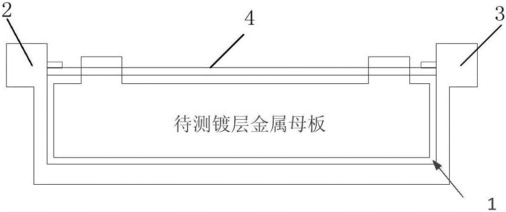
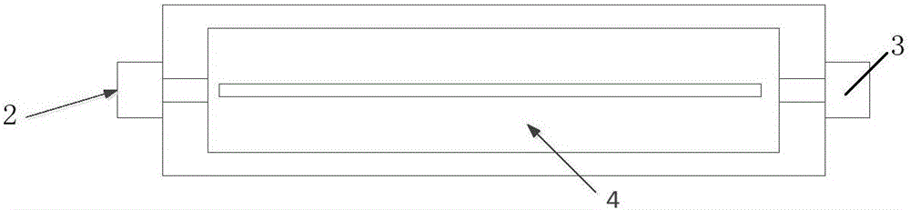
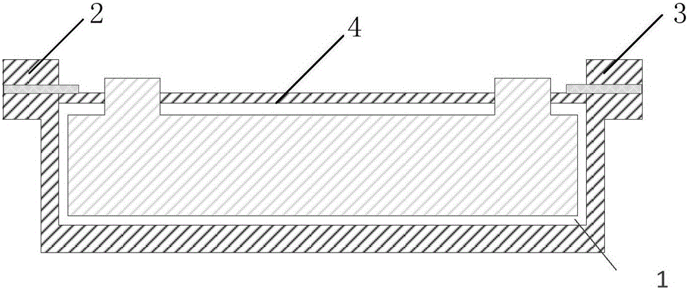
[0024] Refer to Figure 1(a), Figure 1(b), figure 2 and image 3 The broadband non-contact coating passive intermodulation test device based on the transmission line structure of the present invention includes a microstrip transmission line, a first low-frequency coaxial connector 2, a second low-frequency coaxial connector 3 and a PIM tester 5, One end of the transmission line is connected to the PIM tester 5 through the first low-frequency coaxial connector 2, and the other end of the microstrip transmission line is connected to the PIM tester 5 through the second low-frequency coaxial connector 3, and the plating metal motherboard to be tested Located in the dielectric layer 1 of the microstrip transmission line.

[0025] It should be noted that the middle portion of the upper conductor 4 of the microstrip transmission line is provided with a through hole, the d...


PUM


Abstract

A broadband non-contact plating passive intermodulation testing device based on a transmission line structure is disclosed. The device comprises a microstrip transmission line, a first low-frequency coaxial connector, a second low-frequency coaxial connector and a PIM tester. One end of the microstrip transmission line is connected to the PIM tester through the first low-frequency coaxial connector, and the other end of the microstrip transmission line is connected to the PIM tester through the second low-frequency coaxial connector. A plating metal mother board to be tested is in a medium layer of the microstrip transmission line. Intermodulation index testing results of the device are highly targeted and accurate.

Description

Technical field [0001] The invention belongs to the technical field of plating testing, and relates to a broadband non-contact plating passive intermodulation testing device based on a transmission line structure. Background technique [0002] When two or more carrier signals pass through a component with a nonlinear response, a new signal different from the carrier frequency will be generated. This phenomenon is called passive intermodulation. Passive intermodulation (PIM) refers to the spurious signals generated by the mixing of two or more frequency transmitting carriers in passive nonlinear devices, which have caused serious interference to modern high-power, multi-channel communication systems . [0003] At present, the passive intermodulation test of coating materials is mainly based on a specific laboratory environment. The general plan for passive intermodulation testing of materials and coatings is basically based on the existing coaxial or waveguide, by changing the mat...

Claims


Application Information

Patent Timeline
IPC IPC(8): G01N27/00
CPCG01N27/00
Inventor 贺永宁陈雄
Owner XI AN JIAOTONG UNIV
Why Eureka
Try Eureka