
Method for detection of machining deviation of crtsⅢ track plate

A deviation detection, track plate technology, applied in the direction of measuring devices, geometric CAD, instruments, etc., can solve the problem of inability to realize the refined three-dimensional reconstruction of the surface model of the track plate, the detection of the processing deviation of the track plate, and the skew value of the embedded casing Unable to detect and other problems to achieve the effect of reducing omissions, avoiding arbitrariness, and reducing personnel investment

Active Publication Date: 2019-03-29
CHINA RAILWAY DESIGN GRP CO LTD
View PDF2 Cites 0 Cited by
  • Summary
  • Abstract
  • Description
  • Claims
  • Application Information

AI Technical Summary

Problems solved by technology

Due to the limited number of laser beams on the inner surface of the rail platform, only about 6 points per plane are obtained. Therefore, this method cannot completely reconstruct the fine model of each plane
[0006] Chinese Invention Patent Publication No. CN103697813A discloses a ballastless track slab size detection method and device. Although this method realizes the automatic detection of CRTSⅢ track slab appearance size deviation, the method also has the following disadvantages: (1) it needs to be tested The surface of the ballastless track slab is equipped with multiple photometric points and coded marking points, and two standard rulers are placed above the track slab. Before the track slab is inspected, these devices need to be manually installed on the board to be inspected, and complete automation cannot be realized. Detection; (2) the method is by laying a certain number of photometric points on the track plate to be detected, and adopting a light-reflecting mark or a laser transmitter to project a laser point. The algorithm extracts the edge features, and then fits the three-dimensional coordinates of the center point of the photographic measurement points. The characteristics of this method require that these photographic measurement points must be arranged in the plane area of ​​the inner surface of the rail platform. Such photogrammetry points cannot be arranged in the shaped area, and the number of photogrammetry points arranged by this method is limited. Based on the limited number of laser points, the refined 3D reconstruction of the surface model of the track slab cannot be realized; (3) the photogrammetry method is used to achieve Track plate detection can only obtain the three-dimensional coordinates of the photogrammetry points. If laser scanning is used, massive laser point clouds on the surface of the track plate can be directly obtained
However, this method has the following disadvantages: (1) When detecting the relative dimensional deviation of the embedded casing of the track plate, it is necessary to use the spherical self-centering tool, scan the point cloud of the spherical model on the top of the self-centering tool, fit the spherical model, and then By calculating the three-dimensional space distance of the center point of the fitting spherical model, the center distance of the embedded casing of the same rail platform is indirectly detected; (2) During the laser scanning of the track plate, insert the self-returning spherical tooling into the center of the embedded casing, and automatically The bottom plane of the centering tooling is in contact with the rail surface, and the central axis of the entire tooling is parallel to the normal vector of the rail surface, so the deflection value of the embedded casing required in the inspection specification cannot be detected
(3) During the inspection of the track slab, only the inspection items required in the track slab inspection specification are tested, and the detection of the overall processing deviation of the track slab is not realized

Method used


Image

  • Method for detection of machining deviation of crtsⅢ track plate
  • Method for detection of machining deviation of crtsⅢ track plate

Examples


Embodiment Construction

[0038] The detection method of the present invention will be described in detail below with reference to the accompanying drawings.

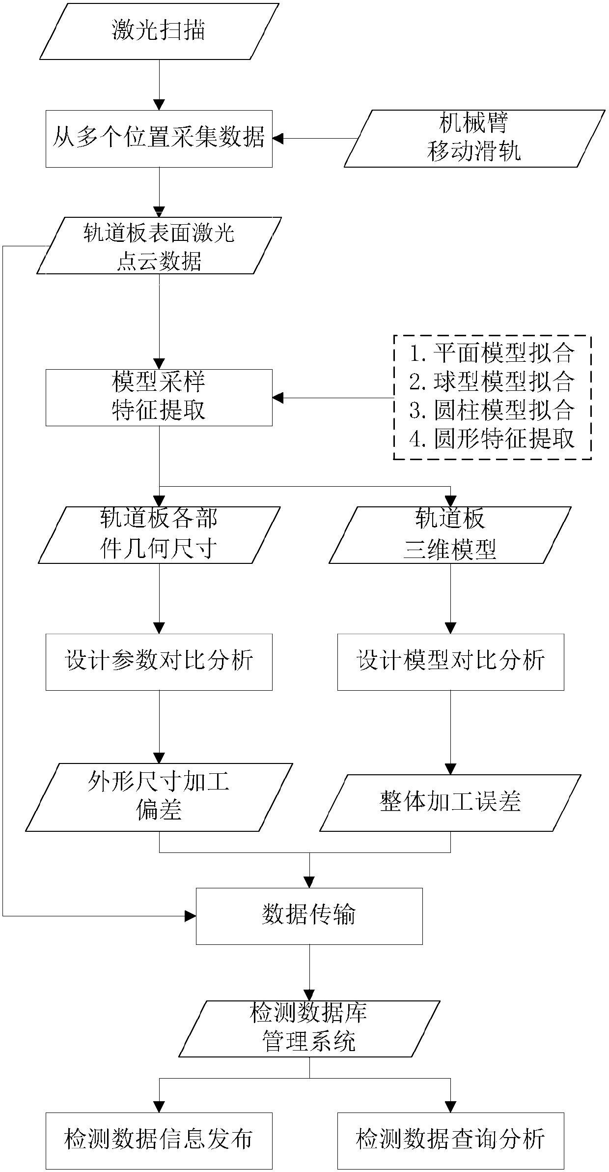
[0039] like figure 1 As shown, the method for detecting the deviation of the outer dimension of the CRTS III track plate of the present invention comprises the following steps:

[0040] A CRTS III type track plate processing deviation detection method, comprising the following steps:

[0041] S1. Use a robotic arm and / or a mechanical slide, and a laser scanning system to scan the track plate from multiple positions, and correct the data collected from multiple positions into laser point cloud data on the track plate surface in a unified coordinate system ;

[0042] S2, using the model random sampling consistency algorithm to automatically extract the model of each component of the track plate from the laser point cloud data, and obtain the geometric dimensions of each component of the track plate;

[0043] S3. Compare the obtained geometric ...


PUM


Abstract

The invention discloses a CRTS (Slab Ballastless Track) III type track slab machining deviation detection method. The method comprises the following steps: scanning a track slab by a laser scanning system of a mechanical arm and / or a mechanical slide track, correcting acquired data into track slab surface laser point cloud data of a unified coordinate system; automatically extracting component models of the track slab from the laser point cloud data, and acquiring geometrical sizes of components of the track slab; comparing the acquired geometrical sizes of the components of the track slab with design parameters of the track slab, and calculating an overall dimension machining deviation of the track slab; and comparing the track slab surface laser point cloud data with a three-dimensional design model of the track slab to obtain an overall machining deviation of the track slab, managing track slab detection data in a database way, and uploading original detection data and result data to a remote server in real time to realize informatization management of track slab detection results through a network release system. The method has the advantages of high detection efficiency, low personnel investment and no need of detection tools.

Description

technical field [0001] The invention relates to the field of high-speed railway track slab detection, in particular to a high-speed railway CRTS III type track slab processing deviation detection method. Background technique [0002] CRTS (slab ballastless track) III type ballastless track is composed of steel rails, fasteners, prefabricated ballastless track slabs, self-compacting concrete, limit structures, intermediate isolation layers (geotextiles) and reinforced concrete bases. The ballastless track slab of type CRTS III is a new type of ballastless track slab developed and formed with complete independent intellectual property rights in my country. The structure of CRTSⅢ type ballastless track slab is similar, generally as follows figure 2 As shown, it mainly includes a bottom plane 10 , a rail bearing platform 11 and a pre-embedded sleeve 12 , wherein the rail bearing platform 11 includes a bottom rail bearing surface and jaw surfaces on both sides. Because it is a ...

Claims


Application Information

Patent Timeline
Patent Type & Authority Patents(China)
IPC IPC(8): G06F17/50G01B11/00
CPCG01B11/00G06F30/17G06F30/367
Inventor 许磊王长进李新增李亚辉谭兆谷洪业石德斌康占龙铁骊山
Owner CHINA RAILWAY DESIGN GRP CO LTD
Learn More