A Method for Prediction of Strip Warp Suitable for Continuous Annealing Units

A continuous annealing unit and strip steel technology, applied in the field of metallurgical steel rolling, can solve problems such as the study of the force of the internal unit of the strip steel, the inability to realize the online prediction of the bending of the strip, and the inability to quantitatively give the bending trend of the strip steel. Minimize the effect of avoiding broken belt accidents and improving production efficiency

Active Publication Date: 2019-03-22
唐山格诺金属科技有限公司
View PDF5 Cites 0 Cited by
  • Summary
  • Abstract
  • Description
  • Claims
  • Application Information

AI Technical Summary

Problems solved by technology

Most of the previous scholars were based on the research on the strip from elastic instability to buckling [1-5] , or the influence of the total set tension of the strip on the buckling, there is no in-depth study on the force of the internal unit of the strip, not only cannot realize the online prediction of the buckling, but also cannot quantitatively give the Strip trend

Method used


Image

  • A Method for Prediction of Strip Warp Suitable for Continuous Annealing Units
  • A Method for Prediction of Strip Warp Suitable for Continuous Annealing Units
  • A Method for Prediction of Strip Warp Suitable for Continuous Annealing Units

Examples


Embodiment 1

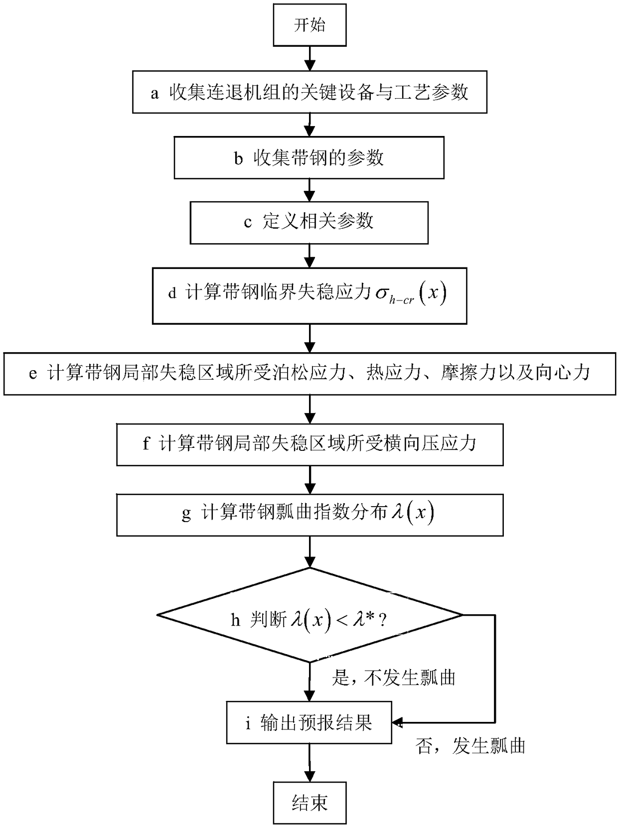
[0059] according to figure 1 The overall calculation flow chart of the strip bending prediction method suitable for the continuous annealing unit is shown. The steel strip is selected as CQ and the specification is 0.50mm×1500mm, and a certain pass of the soaking section of the continuous annealing unit in a domestic factory is taken as example:

[0060] First, in step 1, the key equipment and process parameters of the continuous annealing unit are collected, mainly including: furnace roll radius R=450mm, furnace roll straight section length S=600mm, furnace roll taper γ=0.002rad, critical taper γ c = 0.004rad, unit speed V = 6m / s, speed influence coefficient κ = 0.12, friction coefficient μ between strip steel and furnace roll = 0.15;

[0061] Subsequently, in step 2, the parameters of the strip are collected, mainly including: strip width B=1500mm, strip thickness h=0.5mm, tension distribution σ of the current process section j (x) (such as Figure 4 shown), the tension d...

Embodiment 2

[0081] Select the strip steel whose steel type is CQ and whose specification is 0.50mm×1500mm, and take a certain pass in the slow cooling section of a continuous annealing unit in a domestic factory as an example:

[0082]First, in step 1, the key equipment and process parameters of the continuous annealing unit are collected, mainly including: furnace roll radius R=450mm, furnace roll straight section length S=400mm, furnace roll taper γ=0.003rad, critical taper γ c = 0.004rad, unit speed V = 6m / s, speed influence coefficient κ = 0.12, friction coefficient μ between strip steel and furnace roll = 0.15;

[0083] Subsequently, in step 2, the parameters of the strip are collected, mainly including: strip width B=1500mm, strip thickness h=0.5mm, tension distribution σ of the current process section j (x) (such as Figure 12 shown), the tension distribution σ of the previous process section j-1 (x) (such as Figure 13 shown), the temperature distribution T(x) of the current pr...


PUM

PropertyMeasurementUnit
widthaaaaaaaaaa
thicknessaaaaaaaaaa

Abstract

A strip steel buckles forecast method suitable for a continuous withdrawal unit, mainly comprises the following steps that are executed by a computer: 1 collecting a key apparatus of the continuous withdrawal unit and a technological parameter; 2 collecting the strip steel parameter; 3 defining related parameters; 4 calculating a strip steel critical instability stress Sigmah-cr(x); 5 calculating a Poisson stress Sigmav(x) that is born in strip steel local instability area, a thermal stress SigmaT(x), a frictional force Taud(x), and a centripetal force Tauz(x); 6 calculating a transversal crushing stress Sigmah(x) that is born in strip steel local instability area; 7 calculating strip steel buckles index distribution Lambada(x); 8 determining if Lambada(x) <Lamada *satisfies; and 9 outputting the forecast result. Buckles forecast in strip steel plate-connecting process is realized, thereby reducing accident rate and raising production efficiency.

Description

technical field [0001] The invention belongs to the technical field of metallurgy and steel rolling, and in particular relates to a method for predicting steel strip warpage. Background technique [0002] Continuous annealing adopts technologies such as rapid heating, high temperature annealing, rapid cooling, and overaging treatment, which can combine cleaning, annealing, smoothing, finishing and other processes into one, and has short production cycle, high efficiency, and is suitable for mass production, etc. It has been widely used due to a series of advantages. However, in the continuous annealing production process, one or several folds of different degrees often appear in the longitudinal direction of the strip, which is called "bending" on site. The buckling phenomenon is extremely harmful to the stability of the unit plate and the quality of the product. At the slightest, there will be tens of meters of wrinkles, which will lead to measures to reduce the speed of t...

Claims


Application Information

Patent Timeline
Patent Type & Authority Patents(China)
IPC IPC(8): G06F17/50C21D1/26C21D11/00C21D9/52
CPCC21D1/26C21D9/52C21D11/00G16Z99/00
Inventor 白振华王云祥王瑞刘亚星周莲莲钱承崔亚亚
Owner 唐山格诺金属科技有限公司
Why Eureka
Try Eureka