Method for installing nameplate of transformer and nameplate installation structure for transformer

A technology of installation structure and installation method, applied in transformer/inductor parts, instruments, display devices, etc., can solve the problems of inconvenience for users to view the content of the nameplate, the position of the nameplate cannot be adjusted at will, and many installation procedures, etc. The effect of wide versatility and improved installation efficiency

Active Publication Date: 2016-10-26
GUANGDONG CHAMPON ELECTRIC CO LTD
View PDF6 Cites 2 Cited by
  • Summary
  • Abstract
  • Description
  • Claims
  • Application Information

AI Technical Summary

Problems solved by technology

However, in practical applications, it is often necessary to change the installation position of the nameplate according to the installation situation of the transformer, otherwise it is not convenient for the user to view the content of the nameplate; therefore, it is unreasonable to

Method used


Image

  • Method for installing nameplate of transformer and nameplate installation structure for transformer
  • Method for installing nameplate of transformer and nameplate installation structure for transformer
  • Method for installing nameplate of transformer and nameplate installation structure for transformer

Examples


Embodiment 1

[0030] This embodiment describes a method for installing a nameplate of a transformer. A connecting fitting is clamped at the upper or lower end of the transformer corrugated sheet; the front of the connecting fitting is blocked by the reinforcing rib connected to the front end of the transformer corrugated sheet to limit the forward movement of the connecting fitting; the connecting fitting is located in the transformer The parts on both sides of the corrugated sheet are respectively connected to the nameplate located in front of the transformer corrugated sheet, and the rearward movement of the connecting fitting and the nameplate is restricted by the transformer corrugated sheet blocking behind the nameplate, so that the connecting fitting and the nameplate are co-located and fixed.

[0031] Compared with the traditional transformer nameplate installation method, the transformer nameplate installation method of the present invention removes the restriction that the nameplate ...

Embodiment 2

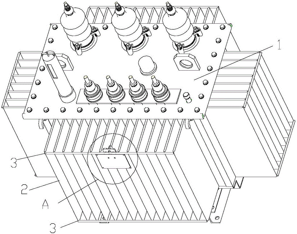
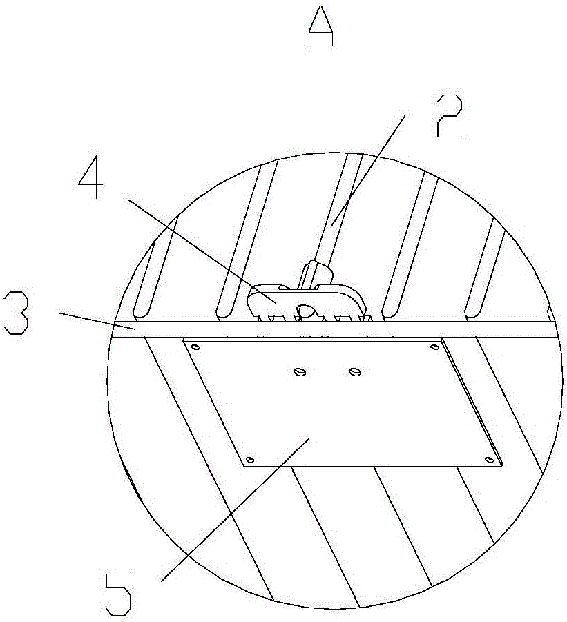
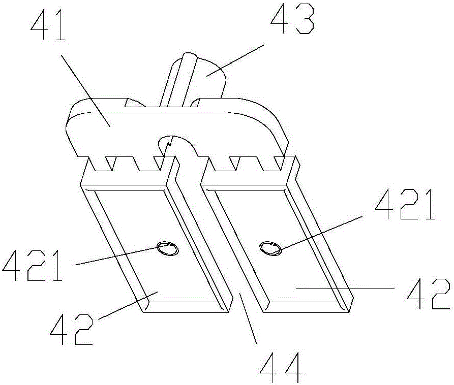
[0034] This embodiment describes a transformer nameplate installation structure, its structure is as follows Figure 1 to Figure 5 Shown; including connection fittings 4, nameplate 5 and transformer; transformer includes transformer body 1, several transformer corrugated sheets 2 longitudinally arranged outside the transformer body 1 and reinforcing ribs 3 connected to the front end of transformer corrugated sheet 2. The connecting fitting 4 includes a connecting block 41 and two mounting blocks 42; the two mounting blocks 42 are respectively arranged on the same side of the connecting block 41; a distance is left between the two mounting blocks 42 to form a clamping channel 44, so that the mounting fittings It is clamped on the upper end of the transformer corrugated sheet 2; two installation blocks 42 are respectively located in the gap between adjacent transformer corrugated sheets 2; the two installation blocks 42 are respectively provided with installation parts; the namep...

Embodiment 3

[0041] The difference between the installation structure of the transformer nameplate in this embodiment and the second embodiment is that: in this embodiment, the connecting fittings are clamped at the lower end of the transformer corrugated sheet; The upper end surface is fitted, and the mounting block can be supported on the upper end surface of the rib to achieve stable fixation. The height difference ΔH between the bottom of the positioning groove and the protruding surface of the mounting block matches the height difference between the lower end surface of the transformer corrugated sheet and the upper end surface of the reinforcing rib.

[0042] The rest of the structure of this embodiment is the same as that of the second embodiment.


PUM


Abstract

The invention provides a method for installing a nameplate of a transformer. The method is characterized in that a connecting fitting is clamped at an upper end or a lower end of a transformer corrugated plate; on the basis of blocking of a reinforced rib connected to the front end of the transformer corrugated plate, forward movement limiting of the connecting fitting in front of the connecting fitting is realized; and the parts, at the two sides of the transformer corrugated plate, of the connecting fitting are connected with a nameplate before the transformer corrugated plate and backward movement limiting of the connecting fitting and the nameplate is realized because of blocking of the transformer corrugated plate at the rear of the nameplate, so that the connecting fitting and the nameplate are localized and fixed jointly. According to the method, the nameplate can be installed at several positions of the transformer flexibly; and the operation becomes simple and convenient and the installation efficiency is high. In addition, the invention also provides a transformer nameplate installation structure that has advantages of simple structure, convenient production and processing, and high universality and is capable of installing a nameplate at several positions of the transformer flexibly.

Description

technical field [0001] The invention relates to the technical field of transformer nameplate installation, and more specifically relates to a transformer nameplate installation method and a transformer nameplate installation structure thereof. Background technique [0002] Each transformer needs to be equipped with a nameplate to indicate technical data such as the manufacturer's name, rated capacity, rated voltage, rated current, rated impedance, and wiring group. The commonly used nameplate installation method is to pre-weld the bottom plate at the middle of the reinforcing rib on the front of the low-voltage side of the transformer corrugated sheet, and then use screws and other connectors to fix the nameplate to the bottom plate. However, in practical applications, it is often necessary to change the installation position of the nameplate according to the installation situation of the transformer, otherwise it is not convenient for the user to view the content of the nam...

Claims


Application Information

Patent Timeline
IPC IPC(8): H01F27/00G09F7/18
CPCG09F7/18H01F27/00
Inventor 周月梅梁生金东煜李雪梅王国萱
Owner GUANGDONG CHAMPON ELECTRIC CO LTD
Why Eureka
Try Eureka