Supercharge Your Innovation With Domain-Expert AI Agents!

Compressor and junction box cover

A compressor and junction box technology, applied in the field of compressors, can solve the problems of cumbersome wiring steps and high height of the junction box cover, and achieve the effects of saving space, reducing height, and reducing wiring and assembly steps.

Active Publication Date: 2019-05-17
SHANGHAI HITACHI ELECTRICAL APPLIANCES CO LTD
View PDF6 Cites 0 Cited by
  • Summary
  • Abstract
  • Description
  • Claims
  • Application Information

AI Technical Summary

Problems solved by technology

However, for the cylindrical connection terminal 140, it has the following disadvantages: 1) the existing wiring steps usually insert the lead wire 141 on the connection terminal 140 first, and then cover the lead wire 141 and the terminal terminal with the junction box cover 150 140, to protect it from the influence of rainwater and dust, but such wiring steps are relatively cumbersome; 2) Since the lead wires 141 and pins 131 are respectively connected to the two ends of the round terminal 140, in order to ensure that the terminal box cover 150 can be connected smoothly Cover the cylindrical terminal 140 and do not interfere with each other, reserve a larger space between the junction box cover 150 and one end of the connecting end lead 141 of the cylindrical terminal 140 (such as figure 2 As shown, a space of height h is reserved), so the height of the junction box cover is high, which is very unfavorable for some compressors with height restrictions
Similarly, a similar problem arises for flag terminals

Method used


Image

  • Compressor and junction box cover
  • Compressor and junction box cover
  • Compressor and junction box cover

Examples


Embodiment Construction

[0044] Example embodiments will now be described more fully with reference to the accompanying drawings. Example embodiments may, however, be embodied in many forms and should not be construed as limited to the embodiments set forth herein; rather, these embodiments are provided so that this disclosure will be thorough and complete, and will fully convey the concept of example embodiments to those skilled in the art. The same reference numerals denote the same or similar structures in the drawings, and thus their repeated descriptions will be omitted.

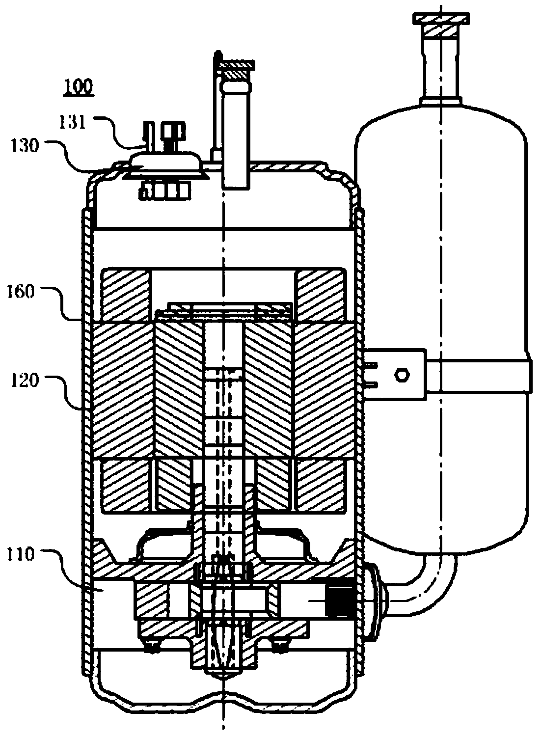
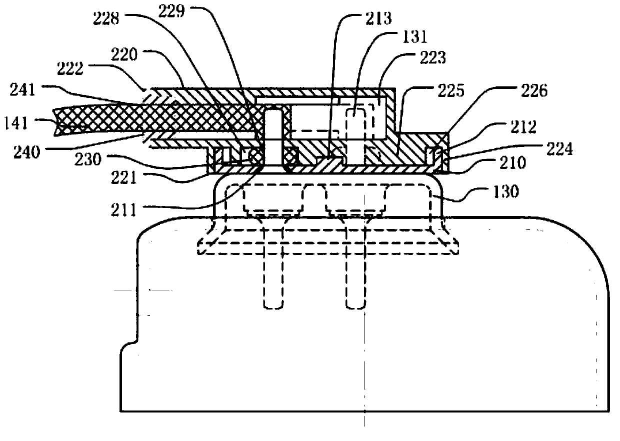
[0045] In order to improve the defects of the prior art, the present invention provides a compressor and its connection terminals. The compressor provided by the present invention can refer to figure 1 , The compressor 100 includes a casing 160, a compression unit 110, a motor unit 120, a wiring mechanism 130 and a junction box cover.

[0046] The compression unit 110 is preferably a rotor type compression unit, which compress...


PUM


Abstract

The invention provides a compressor and a junction box cover. The junction box cover comprises a lower cover and an upper cover, wherein the lower cover comprises at least one first through hole, thefirst through hole is used for a pin of the compressor to penetrate through, the upper cover is connected with the lower cover, the upper cover comprises an upper cover shell, at least one second through hole and at least one third through hole, an accommodating space is formed on the upper cover shell, a first side of the upper cover shell is opposite to the lower cover, the at least one second through hole is formed in the first side of the upper cover shell, the position of the second through hole is corresponding to the position of the first through hole, the second through hole is used for the pin to penetrate through, the third through hole is formed in a second side of the upper cover shell and is used for connecting a leading-out line of the compressor, the third through hole and the second through hole are connected in the accommodating space so that the leading-out line of the compressor is connected with the pin of the compressor in the accommodating space. With the compressor and the junction box cover, provided by the invention, the reliability is improved.

Description

technical field [0001] The invention relates to the field of compressors, in particular to a compressor and a junction box cover. Background technique [0002] The motor of the existing compressor is generally driven by direct current. The stator lead wire of the motor needs to be connected with the wiring mechanism on the motor case to supply power to the motor. like figure 1 As shown, the motor unit 120 of the compressor 100 is connected to the compression unit 110 through a crankshaft to drive the compression components of the compression unit 110 . The casing 160 of the compressor is provided with a wiring mechanism 130 . The wiring mechanism 130 electrically connects the motor unit 120 with the lead wires, specifically, the motor unit 120 is powered by connecting the pins 131 of the wiring mechanism 130 with the connection terminals of the lead wires. [0003] Existing terminals for lead wires are usually cylindrical terminals or flag-shaped terminals. Cylindrical ...

Claims


Application Information

Patent Timeline
Patent Type & Authority Patents(China)
IPC IPC(8): H02K5/22H02K5/10
CPCH02K5/10H02K5/225
Inventor 沈建芳刘杨张常春郑建东
Owner SHANGHAI HITACHI ELECTRICAL APPLIANCES CO LTD
Features
  • R&D
  • Intellectual Property
  • Life Sciences
  • Materials
  • Tech Scout
  • Unparalleled Data Quality
  • Higher Quality Content
  • 60% Fewer Hallucinations
Learn More