
Underwater illumination lamp based on transmission turbidity measurement principle, and light adjustment method for underwater illumination lamp

A measurement principle, a technology for underwater lighting, applied in lighting devices, lighting and heating equipment, components of lighting devices, etc. effect and other issues, to achieve the effect of improving stability and reliability, reducing measurement errors, and improving quality

Active Publication Date: 2016-10-26
CHANGJIANG SURVEY PLANNING DESIGN & RES
View PDF9 Cites 6 Cited by
  • Summary
  • Abstract
  • Description
  • Claims
  • Application Information

AI Technical Summary

Problems solved by technology

At present, underwater lighting can only meet the needs of ordinary observation in most cases. The lighting control method is relatively simple. Most underwater lighting fixtures cannot be dimmed. And it is adjusted manually according to the on-site environment or by the computer according to the preset instructions. The dimming method cannot be automatically adjusted according to the state of the water environment, which will affect the actual effect of underwater lighting.

Method used


Image

  • Underwater illumination lamp based on transmission turbidity measurement principle, and light adjustment method for underwater illumination lamp
  • Underwater illumination lamp based on transmission turbidity measurement principle, and light adjustment method for underwater illumination lamp
  • Underwater illumination lamp based on transmission turbidity measurement principle, and light adjustment method for underwater illumination lamp

Examples


Embodiment Construction

[0018] The implementation of the present invention will be described in detail below in conjunction with the accompanying drawings, but they do not constitute a limitation to the present invention, and are only examples. At the same time, the advantages of the present invention are clearer and easier to understand through the description.

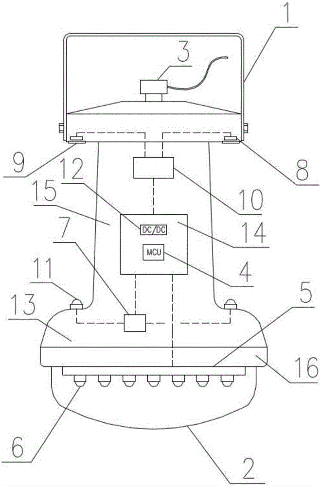
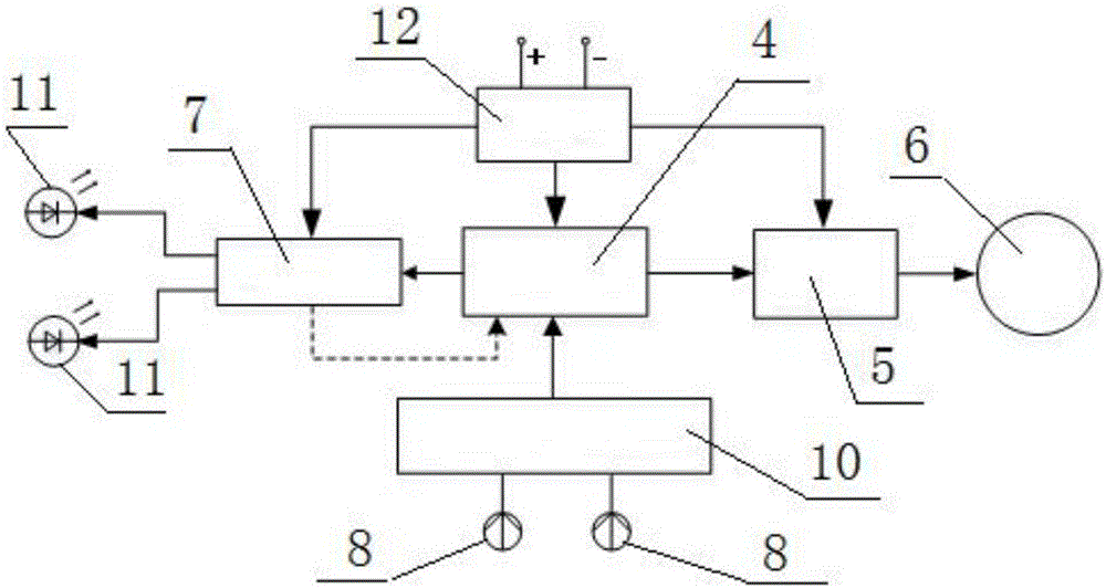
[0019] Referring to the accompanying drawings, it can be seen that the underwater lighting lamp based on the principle of transmission turbidity measurement includes a lamp body 13 located in the water body, and is characterized in that: a lamp bracket 1 is installed on the upper end of the lamp body 13, and a benchmark is installed on the lower end of the lamp body 13. An infrared light source 11, an infrared filter 9 corresponding to the reference infrared light source 11 at the input end is installed on the lamp support 1, and an infrared photoelectric sensor 8 installed on the lamp body 13 is connected to the output end of the infrared f...


PUM


Abstract

The invention discloses an underwater illumination lamp based on the transmission turbidity measurement principle, and discloses the underwater illumination lamp. The lamp comprises a lamp body, a lamp support, a reference infrared light source, an infrared filter, an infrared photoelectric sensor, a cable connector, an LED drive module, an LED lamp, a lampshade housing, a main circuit board, a signal detection processing module, a constant current source drive part, a power module, and a microcontroller. One end of the main circuit board is electrically connected with the signal detection processing module, and the other end of the main circuit board is electrically connected with the constant current source drive part. The LED drive module is electrically connected with the other end of the main circuit board. The infrared photoelectric sensor is electrically connected with an unoccupied end of the signal detection processing module. The reference infrared light source is electrically connected with an unoccupied end of the constant current source drive part. The lamp can automatically adjust the luminous flux, can enable the illuminance of a specific work surface in underwater illumination to be constant, and can improve the quality of underwater illumination. The invention also relates to a light adjustment method for the underwater illumination lamp based on the transmission turbidity measurement principle.

Description

technical field [0001] The invention relates to a lamp for underwater lighting, in particular to a lamp for underwater lighting based on the principle of transmission turbidity measurement. The invention also relates to the dimming method of the underwater lighting fixture based on the transmission turbidity measurement principle. Background technique [0002] Underwater lighting, especially deep water lighting, is widely used in underwater archaeology, cultural relics protection, underwater biological research, underwater scientific experiments, underwater safety protection and other fields. Because water has an obvious attenuation effect on light, and is affected by factors such as water environment changes and water turbidity, underwater lighting is more difficult than ordinary lighting. At present, underwater lighting can only meet the needs of ordinary observation in most cases, and the lighting control method is relatively simple. Most underwater lighting fixtures can...

Claims


Application Information

Patent Timeline
Patent Type & Authority Applications(China)
IPC IPC(8): H05B33/08F21V31/00H05B44/00
CPCF21V31/00H05B45/10
Inventor 谌东海王伟高洪远王环武蒋志勋蔡林杰佘元元赵耀
Owner CHANGJIANG SURVEY PLANNING DESIGN & RES
Learn More