
Optical connectors, cables and optical communication devices

A technology of optical connectors and connectors, applied in the field of optical cables, optical communication devices, and optical connectors, to achieve the effect of preventing adverse effects

Active Publication Date: 2018-06-08
SONY CORP
View PDF5 Cites 0 Cited by
  • Summary
  • Abstract
  • Description
  • Claims
  • Application Information

AI Technical Summary

Problems solved by technology

Moreover, the light-shielding plate covers the emission surface of the optical cable, and thus prevents the parallel light emitted from the emission surface of the optical cable from entering the eyeballs of nearby people and adversely affecting visual functions, etc.

Method used


Image

  • Optical connectors, cables and optical communication devices
  • Optical connectors, cables and optical communication devices
  • Optical connectors, cables and optical communication devices

Examples


Embodiment Construction

[0025] In the following, means for carrying out the present technology are described. Note that description is performed in the following order.

[0026] 1. Structure of optical communication system

[0027] 2. Schematic structure of an optical connector

[0028] 3. The first operation of the optical connector

[0029] 4. The second operation of the optical connector

[0030] 5. Other operations of optical connectors

[0031]

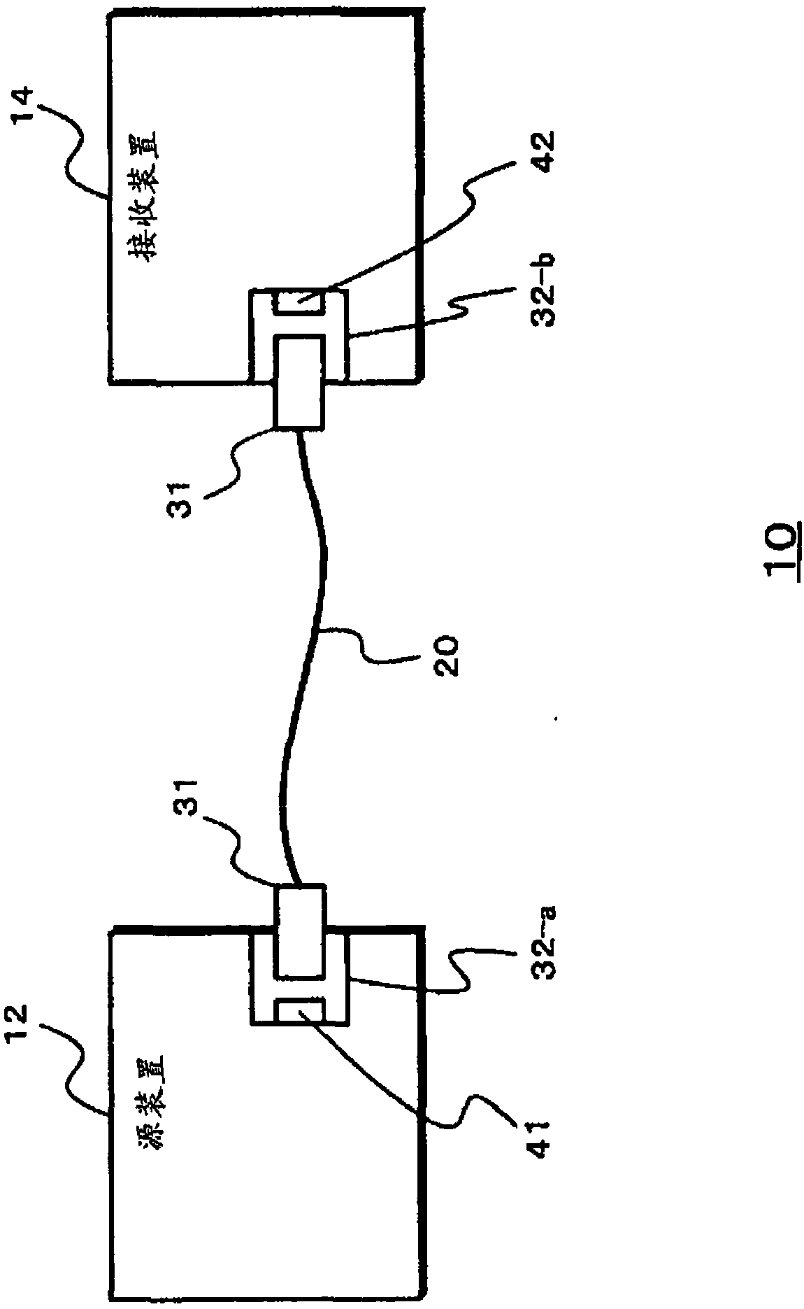
[0032] figure 1 The configuration of an optical communication system using the optical connector of the present technology is explained. In the optical communication system 10 , a source device 12 as an information transmitting side and a receiving device 14 as an information receiving side are connected via an optical transmission path such as an optical cable 20 .

[0033] The source device 12 is a device that can output video and audio content, information of computer data, and the like. For example, the source device 12 is a device such as ...


PUM


Abstract

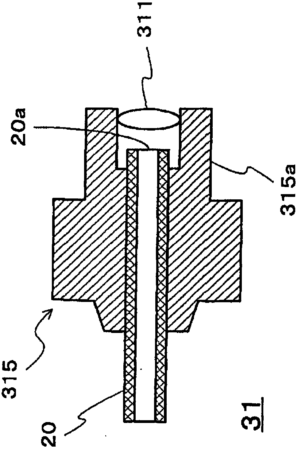
The lens (311) of the plug (31) converts an optical signal from the optical cable (20) into light having a predetermined divergence angle and emits the light. The plug housing (315) is fixed with an optical cable (20) and a lens (311). On the emitting surface (20a) side of the optical cable (20), a lens (311) is placed at a position where an optical signal from the optical cable (20) becomes to have a predetermined divergence angle. The light signal emitted from the plug (31) is divergent when entering the eyeball of a nearby person, and thus is prevented from adversely affecting visual functions and the like.

Description

technical field [0001] The present invention relates to an optical connector, an optical cable, and an optical communication device that prevent optical signals from adversely affecting visual functions and the like. Background technique [0002] In optical communication using laser light, optical cables are connected by, for example, optical connectors. In a well-known optical connector, a lens for collimating optical signals communicated between the plug and receptacle is provided on one of the plug side and the receptacle side, and a lens for collecting parallel light is provided on the other side. . As described above, if communication is performed between the plug and the receptacle by using parallel light, optical communication can be performed without highly accurately positioning the end face of the optical cable at a predetermined interval to face each other with the photodetector, etc., and Inexpensive optical connectors are available. [0003] Furthermore, in P...

Claims


Application Information

Patent Timeline
Patent Type & Authority Patents(China)
IPC IPC(8): G02B6/42
CPCG02B6/3849G02B6/4292G02B2006/4297G02B6/32G02B6/3853
Inventor 铃木和良近藤量资鸟羽一彰中岛康久宫崎敏山本真也
Owner SONY CORP
Learn More