Fly-cutter mechanism

A flying knife, one air chamber technology, applied in metal processing and other directions, can solve the problems of uneven incision, slow manual cutting speed, product damage and so on

Inactive Publication Date: 2016-11-02
镇江奥立特机械制造有限公司
View PDF3 Cites 1 Cited by
  • Summary
  • Abstract
  • Description
  • Claims
  • Application Information

AI Technical Summary

Problems solved by technology

[0002] In the production process of coating, whether it is coated finished products or raw materials, a cutting process is included in the production process. Under the existing technology, manual cutting is generally used. The manual cutting speed is slow, not stable enough, and the cut is uneven. product causing damage

Method used


Image

  • Fly-cutter mechanism
  • Fly-cutter mechanism

Examples


Embodiment Construction

[0011] The following will clearly and completely describe the technical solutions in the embodiments of the present invention with reference to the drawings in the embodiments of the present invention.

[0012] The invention provides a flying knife mechanism, which has the advantages of fast and stable cutting action, straight incision, etc., and is widely used for automatic film cutting of film materials.

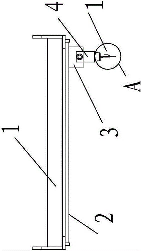
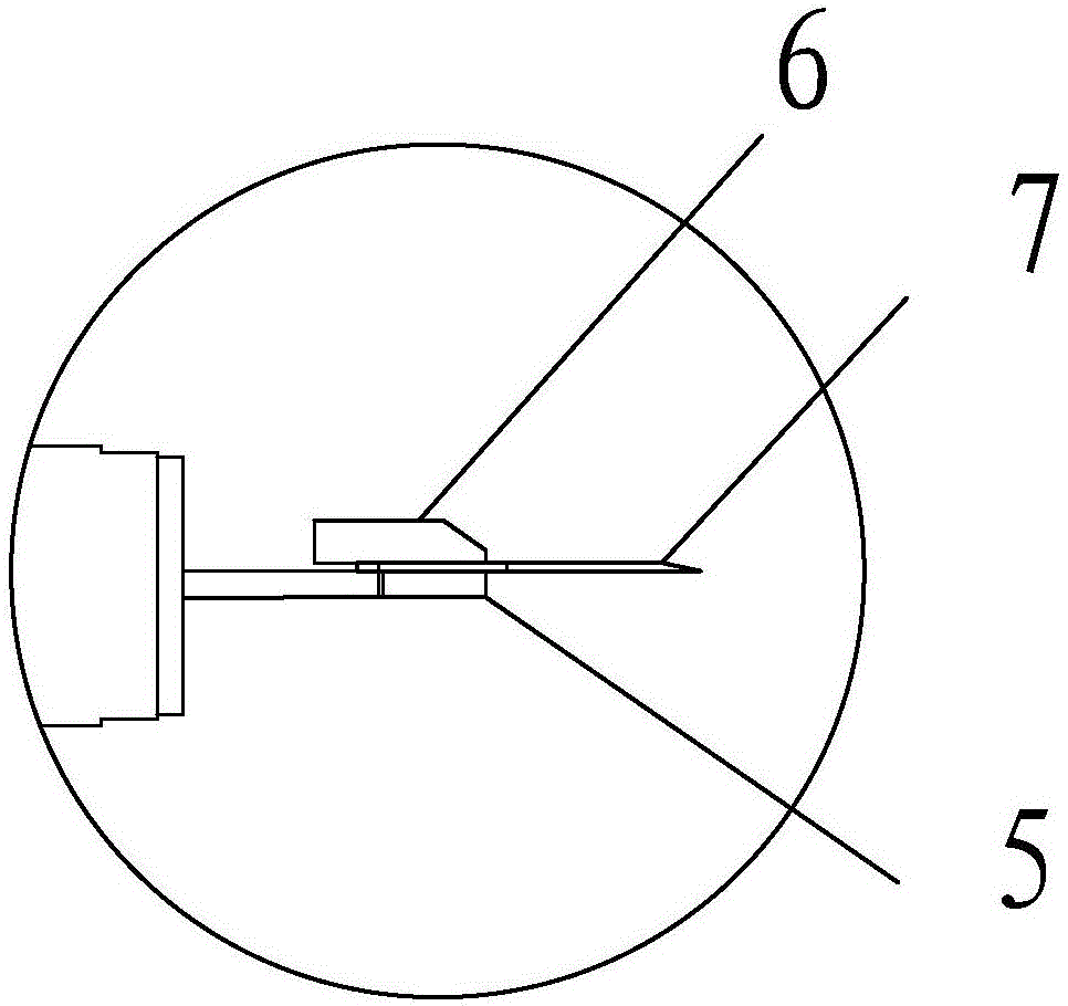
[0013] Such as figure 1 and 2 As shown, a flying knife mechanism is characterized in that it includes a rodless cylinder, the cylinder includes an air chamber 1 and a slide rod 2 positioned below the air chamber 1, the slide rod 2 passes through a slide block 3, the slide A flying knife block 4 is movable on the block 3, and a flying knife 7 is clamped by an upper clamping plate 5 and a lower clamping plate 6 under the flying knife block 4 .

[0014] Implementation: When working, the flying knife 7 on the flying knife block 4 is kept vertical to the slider 2, the cylinde...


PUM


Abstract

The invention provides a fly-cutter mechanism. The mechanism comprises a rodless cylinder, wherein the cylinder comprises an air chamber and a sliding rod located below the air chamber; the sliding rod penetrates through a sliding block; a fly-cutter block is movably arranged on the sliding block; and a fly-cutter is clamped by an upper clamping plate and a lower clamping plate below the fly-cutter block. The fly-cutter mechanism is used for cutting film materials and has the advantages of rapid and steady cutting actions, straight cuts and the like.

Description

technical field [0001] The invention relates to a flying knife mechanism. Background technique [0002] In the production process of coating, whether it is coated finished products or raw materials, a cutting process is included in the production process. Under the existing technology, manual cutting is generally used. The manual cutting speed is slow, not stable enough, and the cut is uneven. product causing damage. Contents of the invention [0003] In order to solve the above technical problems, the present invention provides a flying knife mechanism, which has the advantages of fast and stable cutting action and straight incision, and is widely used for automatic film cutting of film materials. [0004] A flying knife mechanism includes a rodless cylinder, the cylinder includes an air chamber and a slide bar located below the air chamber, the slide bar passes through a slide block, and a flying knife block is movable on the slide block, the flying knife A flying knif...

Claims


Application Information

Patent Timeline
IPC IPC(8): B26D1/60
CPCB26D1/565B26D1/605
Inventor 祝龙云
Owner 镇江奥立特机械制造有限公司
Why Eureka
Try Eureka