Built-in automatic thread trimming mechanism of sewing machine
A thread trimming mechanism and sewing machine technology, which is applied to the thread cutting mechanism, sewing machine components, sewing equipment, etc. in the sewing machine, and can solve the problem of large installation space requirements of the automatic thread trimming mechanism, high configuration cost of the automatic thread trimming mechanism, and the shape of the overlock sewing machine Insufficient aesthetics and other problems, to achieve the effect of beautiful appearance, low noise and small stroke of the whole machine
- Summary
- Abstract
- Description
- Claims
- Application Information
AI Technical Summary
Problems solved by technology
Method used
Image
Examples
Embodiment 1
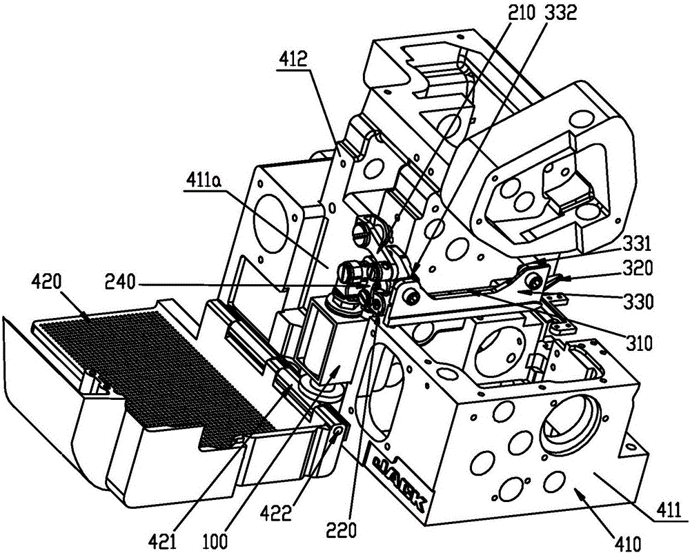
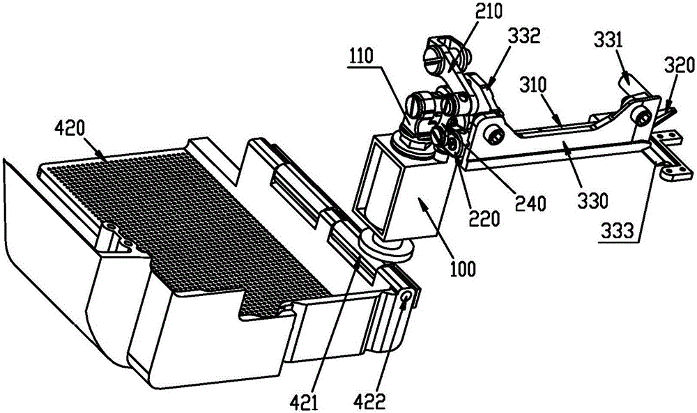
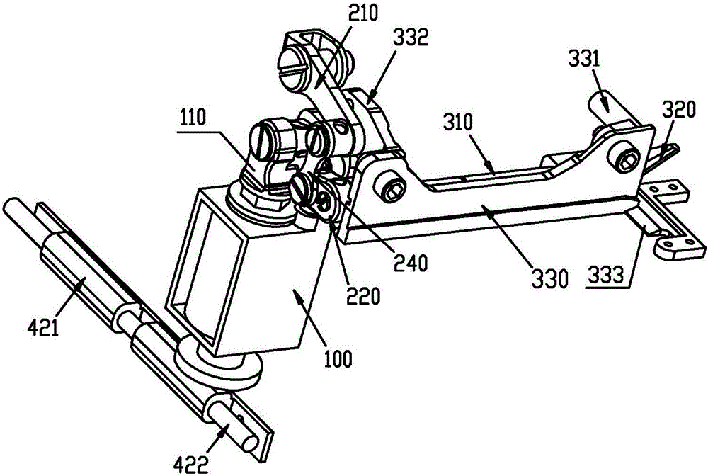
[0044] Such as figure 1 , Figure 4 As shown, a built-in automatic thread trimming mechanism of a sewing machine includes a driving source 100, a first lever 210, a second lever 220, a first connecting rod 230, a second connecting rod 240, a knife shaft 310, a moving knife 320, a knife Seat 330, sewing machine main housing 410, rear cover 420.
[0045] The main housing 410 of the sewing machine includes a base housing 411 and a column housing 412 above it, wherein a recess 411a is formed on the rear wall of the base housing 411 of the sewing machine and below the column housing 412 .
[0046] The driving source 100 is installed in the concave portion 411a. Such as Figure 2 to Figure 4 As shown, the drive source 100 includes a telescopic shaft 110 that expands and contracts in the up and down direction; the upper end of the telescopic shaft 110 is hinged to one end of the first connecting rod 230 through a pin shaft 111, and the other end of the first connecting rod 230 O...
Embodiment 2
[0055] The structure of the built-in automatic thread trimming mechanism of the sewing machine of this embodiment is basically the same as that of Embodiment 1, and the difference between it and Embodiment 1 is as follows: Figure 5 As shown, the flexible connection between the upper end of the telescopic shaft 110 and the first lever 210 is realized through the cooperation of the waist-shaped hole 212 and the pin shaft 111; wherein the waist-shaped hole 212 is arranged on the first lever 210 Above, the pin shaft 111 is connected to the upper end of the telescopic shaft 110 through the waist-shaped hole 212 . Of course, the waist-shaped hole 212 can also be set at the upper end of the telescopic shaft 110, and the pin shaft 111 can be connected with the first lever 210, so that the upper end of the telescopic shaft 110 can be connected with the first lever 210. Articulation between the levers 210.
[0056] The working principle of the built-in automatic thread trimming mechan...
PUM
 Abstract
Description
Claims
Application Information
 - R&D
- Intellectual Property
- Life Sciences
- Materials
- Tech Scout
- Unparalleled Data Quality
- Higher Quality Content
- 60% Fewer Hallucinations
Browse by: Latest US Patents, China's latest patents, Technical Efficacy Thesaurus, Application Domain, Technology Topic, Popular Technical Reports.
© 2025 PatSnap. All rights reserved.Legal|Privacy policy|Modern Slavery Act Transparency Statement|Sitemap|About US| Contact US: help@patsnap.com


