
Attaching device for automatic feeding mechanism and fingerprint identification module

An automatic feeding and driving mechanism technology, applied in the field of machinery, can solve the problems of low transmission efficiency of feeding and receiving workpieces, complex motion structure and control structure, and inconsistent appearance, so as to facilitate viewing or monitoring and simplify Motion trajectory, space-saving effect

Inactive Publication Date: 2016-11-02
SHENZHEN CEWAY TECH
View PDF7 Cites 10 Cited by
  • Summary
  • Abstract
  • Description
  • Claims
  • Application Information

AI Technical Summary

Problems solved by technology

Since the metal shell / metal ring and the cover plate are relatively small workpieces, not only the lamination efficiency is low, but also the lamination error is large, and the appearance after lamination cannot be standardized.
[0003] Existing fingerprint identification module lamination related automation equipment generally requires a relatively large movement process space for the feeding mechanism of the cover plate, or the feeding and receiving and workpiece transmission efficiency is low, and the movement structure and control structure are complex, etc. question

Method used


Image

  • Attaching device for automatic feeding mechanism and fingerprint identification module
  • Attaching device for automatic feeding mechanism and fingerprint identification module

Examples


Embodiment Construction

[0016] The present invention will be further described below in conjunction with the accompanying drawings and embodiments.

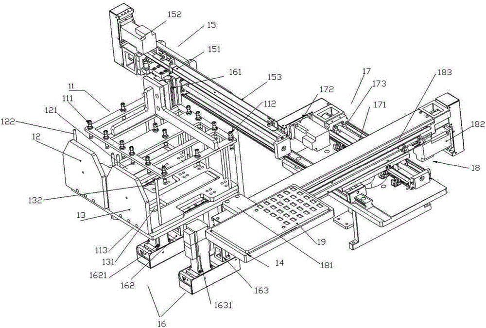
[0017] see figure 1 , is a structural schematic diagram of an embodiment of the automatic feeding mechanism. The automatic feeding mechanism includes a suction cup 11 , a feeding bin 12 , a receiving bin 13 , a working disk 14 , an X-direction driving mechanism 15 and a Z-direction driving mechanism 16 . Wherein, the suction cup 11 is divided into two areas, one area is provided with a feeding suction cup group 111 , and the other area is provided with a material receiving suction cup group 112 . In a preferred solution, the two regions are arranged symmetrically. The feeding bin 12 and the receiving bin 13 are respectively arranged / installed below the feeding suction cup group 111 and the receiving suction cup group 112. The bins 13 are respectively set / installed directly below the feeding suction cup group 111 and the receiving suction cup group 11...


PUM


Abstract

The invention discloses an attaching device for an automatic feeding mechanism and a fingerprint identification module. The attaching device comprises a sucker (11), a feeding bin(12), a receiving bin (13), a work plate (14), an X-direction driving mechanism (15) and Z-direction driving mechanisms (16), wherein a group of feeding suckers (111) arranged relative to the feeding bin (12) and a group of receiving suckers (112) arranged relative to the receiving bin (13) are arranged on the sucker (11). According to the attaching device, the problems in automatic feeding and automatic attaching of a cover plate during an attaching and assembling process of the fingerprint identification module are solved, and the overall production efficiency of the fingerprint identification module can be improved.

Description

technical field [0001] The invention relates to the field of machinery, in particular to a laminating device of an automatic feeding mechanism and a fingerprint identification module. Background technique [0002] With the development of smart phones, the fingerprint identification module has become one of the basic configurations of smart phones. The lamination of the metal shell / metal ring and the cover is an important part of the production of the fingerprint recognition module. Since the metal shell / metal ring and the cover plate are relatively small workpieces, not only the lamination efficiency is low during the lamination process by manual work, but also the lamination error is large, and the appearance after lamination cannot be standardized. [0003] Existing fingerprint identification module lamination related automation equipment generally requires a relatively large movement process space for the feeding mechanism of the cover plate, or the feeding and receiving...

Claims


Application Information

Patent Timeline
Patent Type & Authority Applications(China)
IPC IPC(8): B65G47/91
CPCB65G47/912
Inventor 尹洪萍刘华力
Owner SHENZHEN CEWAY TECH
Learn More