Cable conductor temperature indirect measurement method
A measurement method, cable conductor technology, applied in thermometers, measuring devices, measuring heat, etc., can solve problems such as inability to provide and change
Active Publication Date: 2016-11-02
武汉大云物移智科技有限公司
View PDF6 Cites 18 Cited by
- Summary
- Abstract
- Description
- Claims
- Application Information
AI Technical Summary
Problems solved by technology
The disadvantage of this method is that the thermal parameter values of different materials inside the cable need to be calibrated in the modeling of the cable temperature field, and the manufacturers often cannot provide these parameter values
Even if it can be provided, these values will change greatly in the long-term operation of the cable due to reasons such as aging
Method used
View moreImage
Smart ImageViewing Examples
Examples
Embodiment Construction
Login to View More PUM
 Abstract
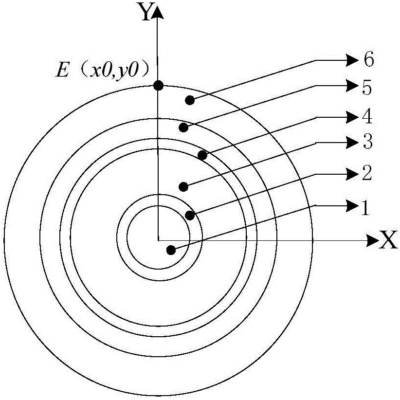
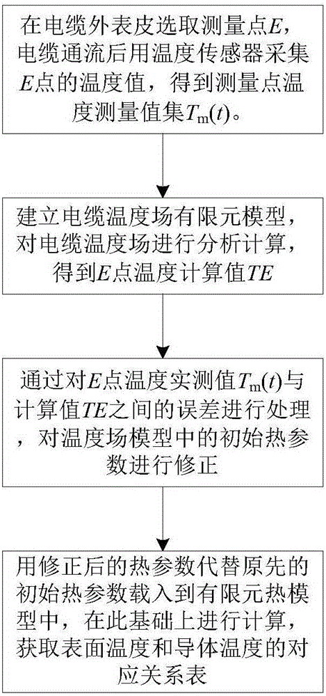
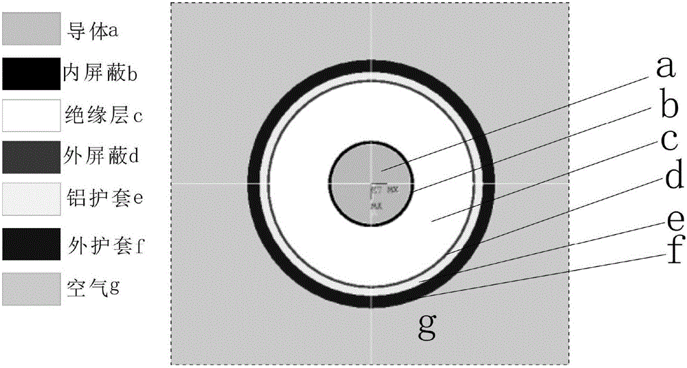
The invention provides a cable conductor temperature indirect measurement method. A measurement point E is selected on the external sheath of a cable, and the cable is electrified and then the temperature value of the point E is acquired by using a temperature sensor so that a temperature measurement value set Tm(t) of the measurement point is obtained; a cable temperature field finite element model is established and analytical calculation is performed on a cable temperature field so that the temperature calculation value TE of the point E is obtained; the error between the actual temperature measurement value Tm(t) of the point E and the calculation value TE is processed so that the initial thermal parameters of the temperature field model are corrected; and the corrected thermal parameters substitute the original initial thermal parameters to be loaded into the finite element thermal model so that a corresponding relation table between surface temperature and conductor temperature is acquired, and conductor temperature is obtained by using a table loop-up mode after measuring surface temperature. The thermal parameters of the internal material of the cable are identified so that the temperature field model of the cable is corrected. The correct corresponding relation between surface temperature and conductor temperature is obtained on the basis of the corrected temperature field model so that conductor temperature is indirectly obtained through measurement of surface temperature.
Description
technical field The invention relates to the technical field of transmission cables, in particular to an indirect temperature measurement method for cable conductors. Background technique Power cables are the core carrier of urban power transmission and distribution networks, and their use has been increasing in recent years. During the operation of the cable, due to the current flowing through the conductor core, the Joule loss of the core, the loss of the main insulation medium and the loss of the metal sheath, etc., cause the temperature of the cable conductor to rise. Excessive conductor temperature will accelerate the aging of materials, shorten the service life of cables, and even cause breakdown accidents. Therefore, from the perspective of the safe operation of the power cable itself, it is necessary to monitor the conductor temperature of the power cable in real time. It is difficult to directly measure the temperature of cable conductors through sensors during c...
Claims
Login to View More Application Information
Patent Timeline
 IPC IPC(8): G01K7/02
CPCG01K7/02
Inventor 张宇娇黄雄峰吴馨徐彬昭
Owner 武汉大云物移智科技有限公司
Features
- R&D
- Intellectual Property
- Life Sciences
- Materials
- Tech Scout
- Unparalleled Data Quality
- Higher Quality Content
- 60% Fewer Hallucinations
Learn More Browse by: Latest US Patents, China's latest patents, Technical Efficacy Thesaurus, Application Domain, Technology Topic, Popular Technical Reports.
© 2025 PatSnap. All rights reserved.Legal|Privacy policy|Modern Slavery Act Transparency Statement|Sitemap|About US| Contact US: help@patsnap.com


