Connector

A technology of connectors and connecting arms, which is applied in the direction of connection, fixed connection, and parts of the connection device, etc., and can solve the problems of not giving flexibility to the side joint piece 858

Active Publication Date: 2016-11-02
MOLEX INC
View PDF5 Cites 7 Cited by
  • Summary
  • Abstract
  • Description
  • Claims
  • Application Information

AI Technical Summary

Problems solved by technology

[0009] In the prior art connector, since it is assumed that the current does not flow through the first reinforcing metal fitting 851 and the sec

Method used


Image

  • Connector
  • Connector
  • Connector

Examples


Embodiment Construction

[0104] The following is a more detailed description of an embodiment of the invention with reference to the accompanying drawings.

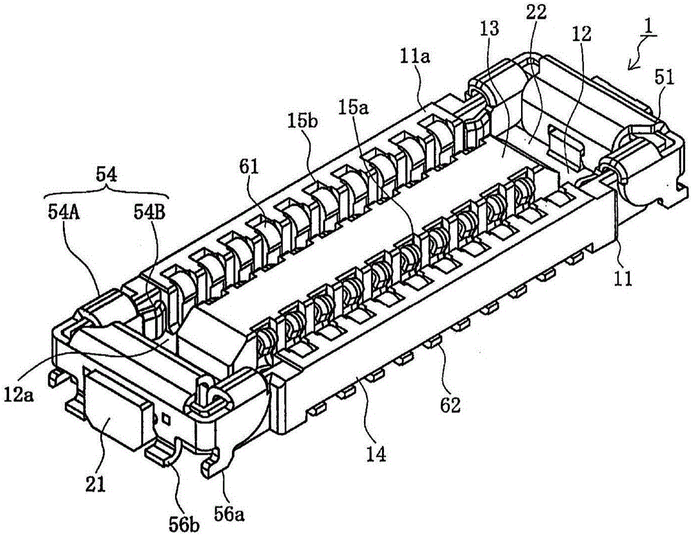
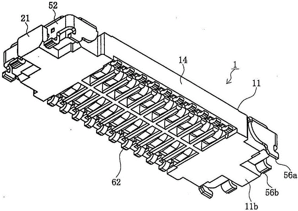
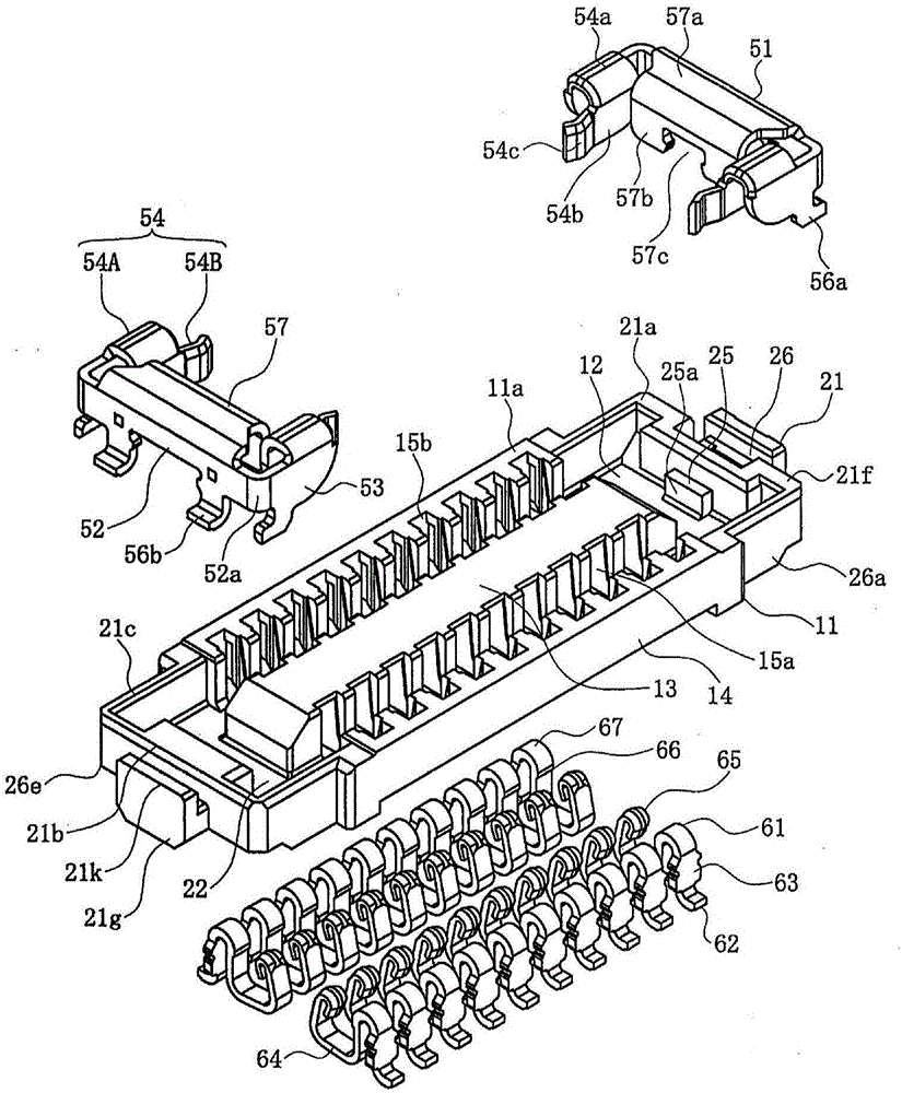
[0105] FIG. 1 is a pair of perspective views of a first connector in an embodiment of the present invention. figure 2 is an exploded view viewed from above of the first connector in this embodiment of the present invention. image 3 is an exploded view viewed from below of the first connector in this embodiment of the present invention. Figure 4 is a side view of the first connector in this embodiment of the present invention. Figure 5 is six views of the first reinforcing metal fitting in this embodiment of the invention. In FIG. 1 , FIG. 1( a ) is a perspective view viewed from above, and FIG. 1( b ) is a perspective view viewed from below. In Fig. 5, Fig. 5 (a) is a front view, Fig. 5 (b) is a side view, Fig. 5 (c) is a rear view, Fig. 5 (d) is made along A-A among Fig. 5 (c) A cross-sectional view of Figure 5 (e) is a top view, and Figur...


PUM


Abstract

A connector is provided which includes a main body, terminals mounted in the body, and a reinforcing metal fitting mounted in the body. The fitting includes a body secured to the mating guide portion, a pair of left and right connecting arm portions connected to the base end of the body, and a pair of left and right contact arm portions connected to the base end of the connecting arm portions. The fitting further includes a first connecting leg portion connected to a connecting pad on a board being connected at the upper end of the first connecting leg portion to the lower end or base end of each contact arm portion so as to have a substantially L-shaped profile when viewed from a side of the connector.The resilient length can be extended to a portion in contact with the other reinforcing metal fitting so as to more reliably maintain the mutual engagement and the electrical connection between the reinforcing metal fitting and the other reinforcing metal fitting.

Description

technical field [0001] The invention relates to a connector. Background technique [0002] Board-to-board connectors are used to electrically connect a pair of parallel circuit boards. These board-to-board connectors are mounted on the mutually facing surfaces of the pair of circuit boards and then butted to establish an electrical connection. It has been proposed that reinforcing metal fittings are installed at both ends as locking members for keeping the two connectors mated (see, for example, Patent Document 1). [0003] Fig. 11 is a pair of perspective views of prior art reinforcing metal fittings, wherein Fig. 11(a) shows a second reinforcing metal fitting, and Fig. 11(b) shows a first reinforcing metal fitting. [0004] In FIG. 11( b ), 851 is a first reinforcing metal fitting installed at both longitudinal ends of the base of the first connector (installed on a first circuit board (not shown)). In FIG. 11( a ), 951 is a second reinforcing metal fitting installed at...

Claims


Application Information

Patent Timeline
IPC IPC(8): H01R13/627H01R13/02H01R12/71
CPCH01R12/716H01R13/02H01R13/6275H01R12/7082H01R12/707H01R12/73H01R13/20H01R12/52H01R12/00H01R13/00
Inventor 武内龙太朗小野洋树笹山直人
Owner MOLEX INC
Why Eureka
Try Eureka