Wire clamp

A wire clamping device and a wire clamping part technology are applied in the field of wire clamping devices, which can solve the problem that the clamping state cannot be stably maintained, and achieve the effects of stable clamping state, easy operation and stable maintenance.

Active Publication Date: 2021-06-01
NAGAKI SEIKI CO LTD
View PDF6 Cites 0 Cited by
  • Summary
  • Abstract
  • Description
  • Claims
  • Application Information

AI Technical Summary

Problems solved by technology

That is, when the force pulling the operating portion 106 is released, the force clamping the linear body 150 disappears, so the clamping state cannot be stably maintained.

Method used


Image

  • Wire clamp
  • Wire clamp
  • Wire clamp

Examples


Embodiment Construction

[0041] Hereinafter, the wire clamp according to the embodiment of the present invention will be described using the drawings.

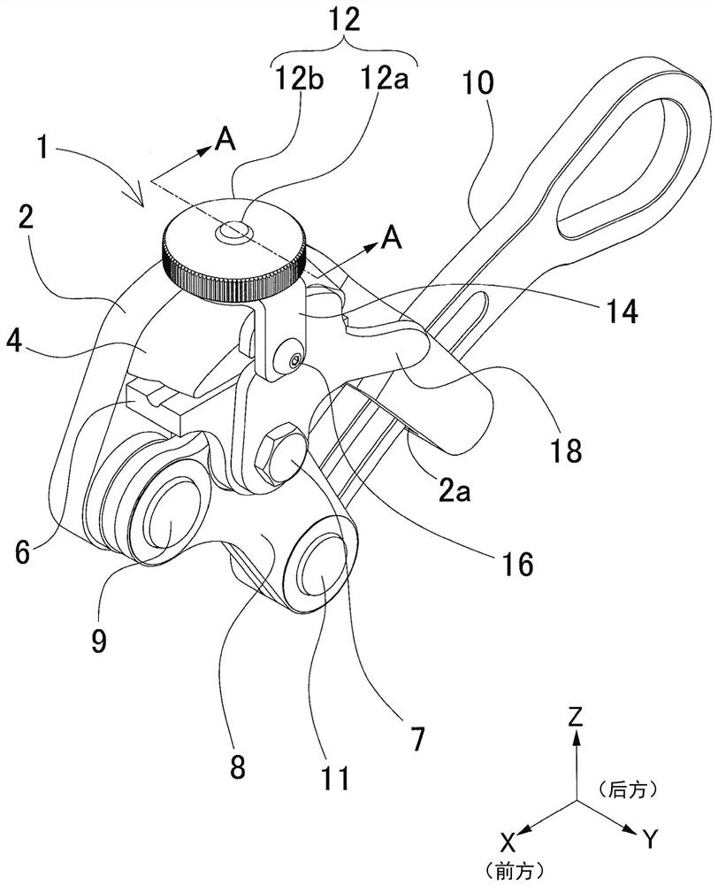
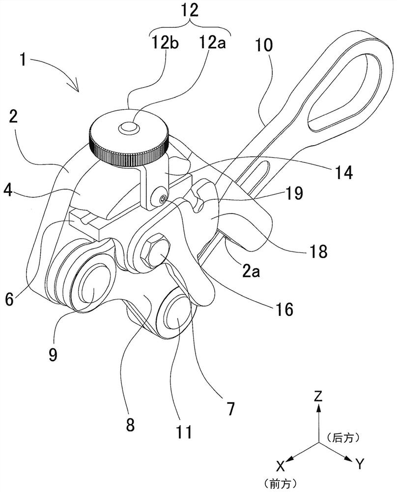
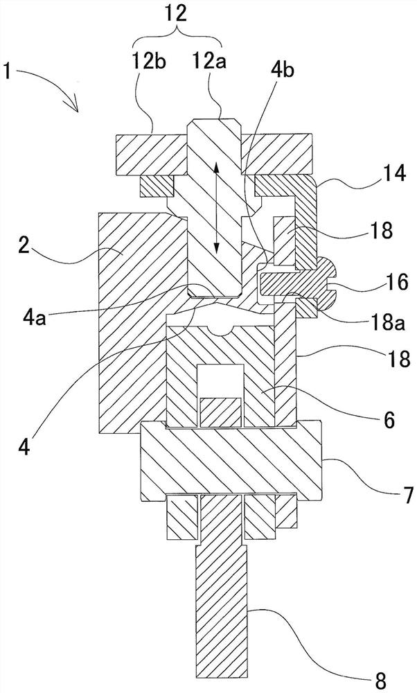
[0042] (first embodiment) figure 1 It is an overall perspective view of the wire gripper 1 of the first embodiment.

[0043] A fixed clamping portion 4 is integrally provided above the substantially flat-shaped main body 2 , and the fixed clamping portion 4 fills one upper side surface of a wire (not shown) that is a linear object to be clamped. The actuating part 8 is swayably supported by the supporting shaft 9 under the fixed thread clamping part 4 . The operating part 10 is pivotally supported on the swing end below the actuating part 8 by the supporting shaft 11 . The swing operation of the operation part 8 is performed by moving the operation part 10 forward and backward. The operation part 10 is slidably disposed through a guide hole 2 a extending rearward of the main body 2 , and is operated back and forth along the guide hole 2 a. At the m...


PUM


Abstract

Provided is a wire gripper capable of performing locking and unlocking operations without lowering work efficiency regardless of the diameter of a linear body to be gripped. Above the main body (2) of the wire gripper (1), a fixed wire gripping portion (4) filled in one side surface of the electric wire is integrally arranged. The actuating part (8) is pivotally supported on the main body (2) in a freely rotatable manner. In addition, the movable clamping part (6) is rotatably supported on the actuating part (8) at a position opposite to the fixed clamping part (4). . The following displacement mechanism is arranged on the fixed clamping part (4), and the threaded part (12) constituted by the threaded shaft (12a) and the handle (12b) operates the displacement supporting part (14) to make it shift. An engagement pin (16) is integrally provided on the displacement support portion (14) so ​​as to be movable in a displacement direction. A hook portion (18) capable of engaging with an engaging pin (16) is rotatably supported on the movable line gripping portion (6). By twisting the handle (12b) in the state where the hook (18) is engaged with the engaging pin (16), the movable wire retaining part (6) is pulled toward the fixed wire retaining part (4) to obtain a locked state .

Description

technical field [0001] The invention relates to a wire gripper, which is used for temporary support of elevator wires, temporary tensioning of communication cables / tram line electric wires, etc., and grips linear objects that generate tension. Background technique [0002] Figure 11 It is a perspective view showing a conventional wire gripper 100 . On the side of the main body 101 of the wire clamp 100 , a fixed wire clamping portion 102 is protruding in the thickness direction, and the fixed wire clamping portion 102 fills one upper side of the linear body 150 as the clamping object. In addition, the actuating part 104 is pivotally supported by the main body 101 by a support shaft 105 so as to be able to swing. Furthermore, the movable thread gripping part 103 is pivotally supported on the actuating part 104 so as to be able to swing. An operation unit 106 for operating the operation unit 104 is pivotally supported on a swing end of the operation unit 104 . The operatio...

Claims


Application Information

Patent Timeline
Patent Type & Authority Patents(China)
IPC IPC(8): H02G1/04H02G7/02
CPCH02G1/04H02G7/02
Inventor 宫迫祥明山本朋也坪冈光司
Owner NAGAKI SEIKI CO LTD
Why Eureka
Try Eureka