
Card connector

A card connector, a card connector technology, applied in the direction of connection, parts of the connection device, electrical components, etc., can solve the problem that the initial position of the connecting member 30 cannot be reliably determined, cannot be restored, and the tray is easy to loosen, etc. problem, achieve reliable determination, prevent falling off, inhibit deformation or breakage

Inactive Publication Date: 2016-11-23
ALPS ALPINE CO LTD
View PDF4 Cites 0 Cited by
  • Summary
  • Abstract
  • Description
  • Claims
  • Application Information

AI Technical Summary

Problems solved by technology

However, after being pressed in, the front end portion 30a of the connecting member 30 may not return to the position where it abuts against the front end side wall 12d of the sliding member 12, and the initial position of the connecting member 30 relative to the tray cannot be reliably determined.
In addition, the tray may become detached easily

Method used


Image

  • Card connector
  • Card connector
  • Card connector

Examples


Embodiment Construction

[0072] Hereinafter, preferred embodiments of the card connector of the present invention will be described.

[0073] In the drawings, the X1 direction represents the insertion direction of the tray, the X2 direction represents the ejection direction of the tray, and the Y1 direction and Y2 direction represent directions perpendicular to the X1-X2 direction when the tray is viewed from above (herein, referred to as the left-right direction). The left direction, the right direction, the Z1 direction, and the Z2 direction represent the up direction and the down direction which are directions (thickness directions) orthogonal to the X1-X2 direction and the Y1-Y2 direction.

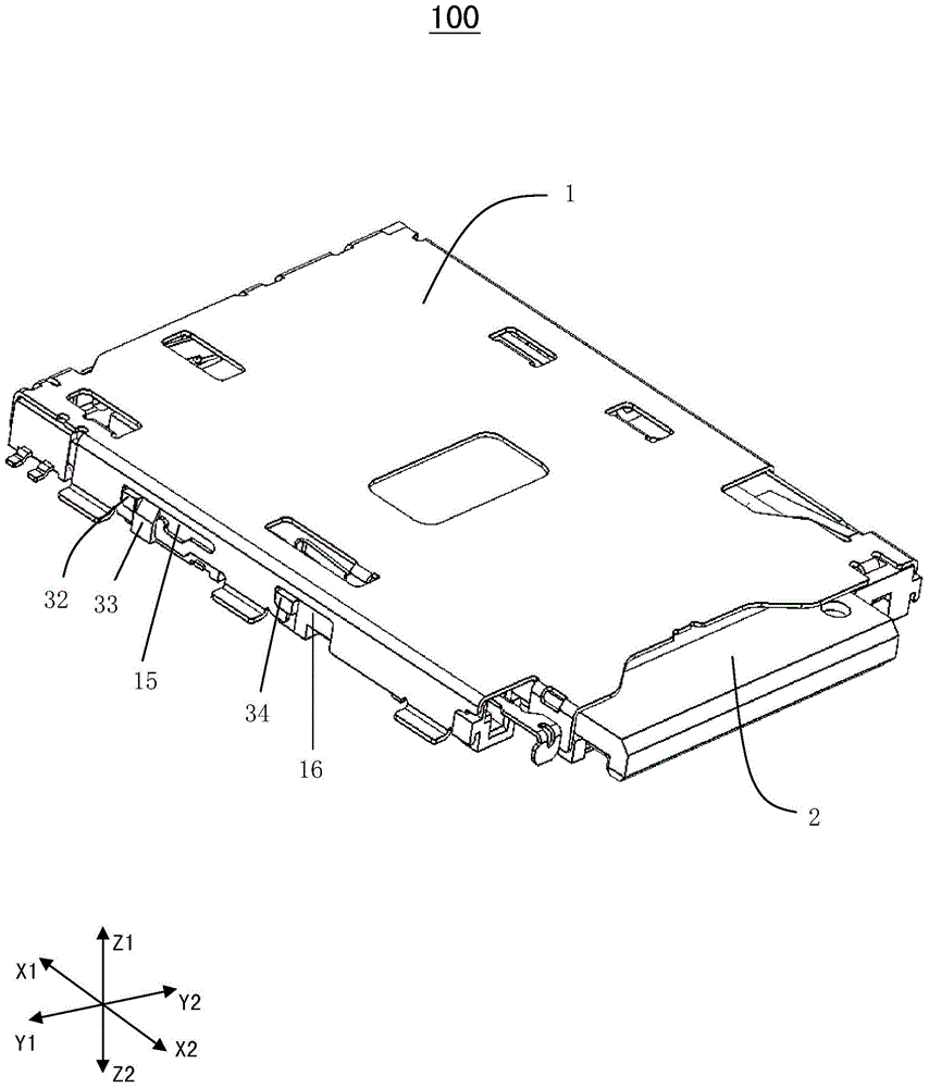
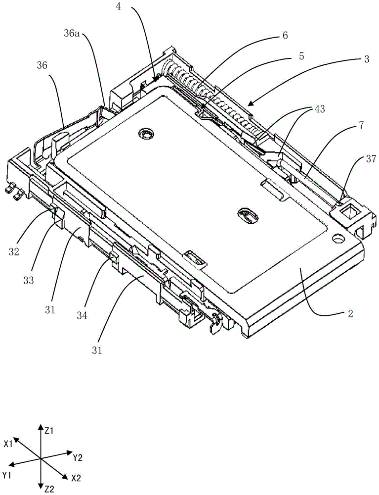
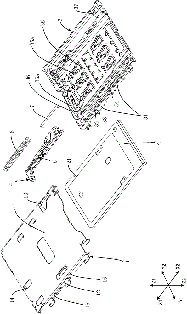
[0074] figure 1 It is an external perspective view of the card connector according to the embodiment of the present invention. figure 2 It is an external perspective view of the card connector omitting the cover member according to the embodiment of the present invention. image 3 It is an exploded perspec...


PUM


Abstract

The invention relates to a card connector. The card connector comprises a casing in which a card is inserted, a tray having a carrying portion capable of carrying the card, a sliding member and a clamping member, wherein the tray can move in the casing and between the connection position electrically connected with the card and the card out-coming position of the casing relative to the casing, the sliding member is mounted on the casing and can move along a tray insertion direction and a tray out-coming direction relative to the casing, the clamping member is composed of elastic members and is arranged on the sliding member, and the clamping member is clamped with the tray at the connection portion to limit movement of the tray relative to the casing. The card connector is characterized in that a limit portion is composed of metals, and the clamping member and the limit portion are in abut connection.

Description

technical field [0001] The present invention relates to a card connector, in particular to a card connector that ensures a stable locking state between a tray and a housing. Background technique [0002] Currently, there are many types of card connectors for connecting SIM cards and memory cards installed in mobile phones, tablet devices, etc., and tray-type card connectors tend to become mainstream recently. A tray-type card connector is generally provided with a leaf spring for preventing the tray from coming off. The convex part of the plate spring is engaged with the concave part provided on the tray to prevent the tray from falling off. In a push-push type card connector, the leaf spring is provided, for example, on a slide member that can slide together with the tray. [0003] For example, Patent Document 1 discloses a push-in type card connector, and specifically discloses the structure of the card connector. The card connector includes: a housing into which a card...

Claims


Application Information

Patent Timeline
Patent Type & Authority Applications(China)
IPC IPC(8): H01R12/71H01R13/627H01R13/629H01R13/502
Inventor 大野真稔
Owner ALPS ALPINE CO LTD
Learn More