High-temperature flue gas waste heat utilization device

A high-temperature flue gas and waste heat technology, which is applied in the direction of heat exchangers, heat exchanger types, heat recovery systems, etc., can solve the problem of reduced heat exchange efficiency between heat exchange components and heat exchange media, affecting heat recovery effects, air particle pollution, etc. problem, to achieve the effect of conveniently and smoothly driving the drive rod, improving the shielding effect, and ensuring the heat exchange effect

Inactive Publication Date: 2021-02-26
潘勇
View PDF6 Cites 3 Cited by
  • Summary
  • Abstract
  • Description
  • Claims
  • Application Information

AI Technical Summary

Problems solved by technology

Some high-temperature flue gas is directly discharged into the outside world, which not only causes air particle pollution and heat pollution, but also causes waste of heat
[0003] Therefore, in the face of high-temperature flue gas treatment, it is necessary to perform heat recovery treatment. The traditional high-temperature flue gas heat recovery device generally has a relatively simple structure. The flue gas is generally directly passed into the interior of the device for heat exchange, and the heat exchange components avoid easy attachment. Dust will reduce the heat exchange efficiency between the heat exchange components and the heat exchange medium, thereby affecting the heat recovery effect, so there are certain limitations

Method used


Image

  • High-temperature flue gas waste heat utilization device
  • High-temperature flue gas waste heat utilization device
  • High-temperature flue gas waste heat utilization device

Examples


Embodiment 1

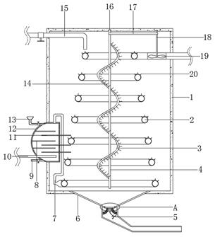
[0029] refer to Figure 1-4 , a high-temperature flue gas waste heat utilization device, comprising a heat exchange tank 1, a water outlet is opened at the bottom of the heat exchange tank 1, and a water outlet bucket 6 is welded on the inner wall of the water outlet, and a heat exchange tank 1 is fixedly installed inside the heat exchange tank 1 The conical spiral air duct 2, and the top outer wall of the heat exchange conical spiral air duct 2 are fixed with equidistantly distributed water guide fins 20, and one side of the heat exchange tank 1 is equipped with a water washing heat exchange mechanism, and the water washing heat exchange The mechanism includes a water washing heat exchange box 12 arranged on one side of the heat exchange tank 1. An air intake pipe 10 is fixedly installed on one side of the bottom end of the water washing heat exchange box 12, and one end of the air intake pipe 10 is provided with a check valve. The inner wall of one side of 12 is fixedly inst...

Embodiment 2

[0038] refer to figure 1 and Figure 5 , a high-temperature flue gas waste heat utilization device. Compared with Embodiment 1, this embodiment also includes an extended hemispherical end 30 fixedly installed on the top side of the heat exchange conical spiral air duct 2, and the extended hemispherical end 30 is connected to the heat exchange tank. The opposite side of 1 is rotatably connected with drive rod 18 by bearing.

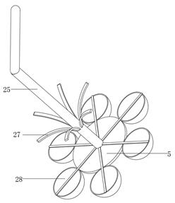
[0039] In the present invention, the bottom end of the driving rod 18 is fixedly connected with fan blades 19 distributed equidistantly, and the middle end of the heat exchange tank 1 is fixed with a bearing seat 16 by bolts, and one side of the fan blade 19 is fixedly installed with fan blades 19 distributed equidistantly. The arc plate 29; the fan blade 19 arranged inside the extended hemispherical end 30 can blow the fan blade 19 in the process of letting out the smoke, thereby driving the driving rod 18 and the rotating rod 4 to rotate; The plate 29 ...


PUM


Abstract

The invention belongs to the technical field of environmental protection, particularly relates to a high-temperature flue gas waste heat utilization device. Aiming at solving the problems that a traditional high-temperature flue gas heat recovery device is generally simple in structure, flue gas is directly introduced into the device for heat exchange, the wall surface of a heat exchange componentis prone to be attached with dust, and then the heat recovery effect is affected, the following scheme is provided. According to the scheme, the novel device comprises a heat exchange tank, a water outlet is formed in the bottom end of the heat exchange tank, and a water outlet hopper is welded to the inner wall of the water outlet. According to the novel device, by arranging an automatic drainage mechanism, when the temperature of water in the heat exchange tank continuously rises, and the internal pressure rises to a certain value, a sealing top plate is pressed to be separated from a fixing ring, so that the water flows out; and in the process of losing magnetic adsorption of magnetic blocks, the water flows out and impacts, along with the water outlet hopper, a flow dividing blockingpiece and a supporting plate with a semispherical plate, so that continuous pulling force is generated on the sealing top plate, and then it is guaranteed that the sealing top plate is far away from the fixing ring, and the automatic drainage is smoothly carried out.

Description

technical field [0001] The invention relates to the technical field of environmental protection, in particular to a device for utilizing waste heat of high-temperature flue gas. Background technique [0002] Air pollution is also called air pollution. According to the definition of the International Organization for Standardization, air pollution usually refers to: due to human activities or natural processes, some substances enter the atmosphere, present a sufficient concentration, reach a sufficient time, and thus endanger the environment. A phenomenon of human comfort, health, and welfare or the environment. Smoke is a mixture of gas and smoke and is the main cause of air pollution in residential areas. The composition of the flue gas is very complex. The gas includes water vapor, sulfur dioxide, nitrogen, oxygen, carbon monoxide, carbon dioxide, hydrocarbons, and nitrogen oxides. The smoke includes fuel ash, coal particles, oil droplets, and pyrolysis products. Therefo...

Claims


Application Information

Patent Timeline
Patent Type & Authority Applications(China)
IPC IPC(8): F28D21/00
CPCF28D21/0014Y02B30/56
Inventor 潘勇
Owner 潘勇
Why Eureka
Try Eureka