
Wall penetrating pipe, wall hole cover and wall penetrating assembly

A technology of passing through the wall pipe and hole cover, applied in the direction of pipes/pipe joints/fittings, pipes, mechanical equipment, etc., can solve the problems of affecting the daily life of households, unable to use wall holes, etc., to facilitate promotion, reduce size requirements, use simple effect

Active Publication Date: 2016-06-08
GD MIDEA AIR-CONDITIONING EQUIP CO LTD +1
View PDF5 Cites 2 Cited by
  • Summary
  • Abstract
  • Description
  • Claims
  • Application Information

AI Technical Summary

Problems solved by technology

[0002] In the existing split-type air conditioner, there are evaporating pipes and condensing pipes connected between the indoor unit located in the room and the outdoor unit located outside the room. When the product is installed, it is usually necessary to open a wall hole on the wall for the evaporating pipe and condensing pipe. Pipes pass through; in response to this installation requirement, when ordinary households carry out interior decoration, they usually set up holes for the evaporation pipe and condensation pipe to pass through the wall at the upper and lower positions of the reserved air conditioner installation position in the living room. Specifically, The upper wall hole can be used for wall-mounted air conditioner installation, and the lower wall hole can be used for floor-mounted air conditioner installation. Of course, some special air conditioners cannot be used when installing the original wall hole, and need to be re-drilled on the wall. This makes at least one wall hole on the wall of the resident idle, so that small animals such as mice and birds outside can enter the room through the wall hole and affect the daily life of the resident.

Method used


Image

  • Wall penetrating pipe, wall hole cover and wall penetrating assembly
  • Wall penetrating pipe, wall hole cover and wall penetrating assembly
  • Wall penetrating pipe, wall hole cover and wall penetrating assembly

Examples


Embodiment Construction

[0058] In order to understand the above-mentioned purpose, features and advantages of the present invention more clearly, the present invention will be further described in detail below in conjunction with the accompanying drawings and specific embodiments. It should be noted that, in the case of no conflict, the embodiments of the present application and the features in the embodiments can be combined with each other.

[0059] In the following description, many specific details are set forth in order to fully understand the present invention. However, the present invention can also be implemented in other ways different from those described here. Therefore, the protection scope of the present invention is not limited by the specific details disclosed below. EXAMPLE LIMITATIONS.

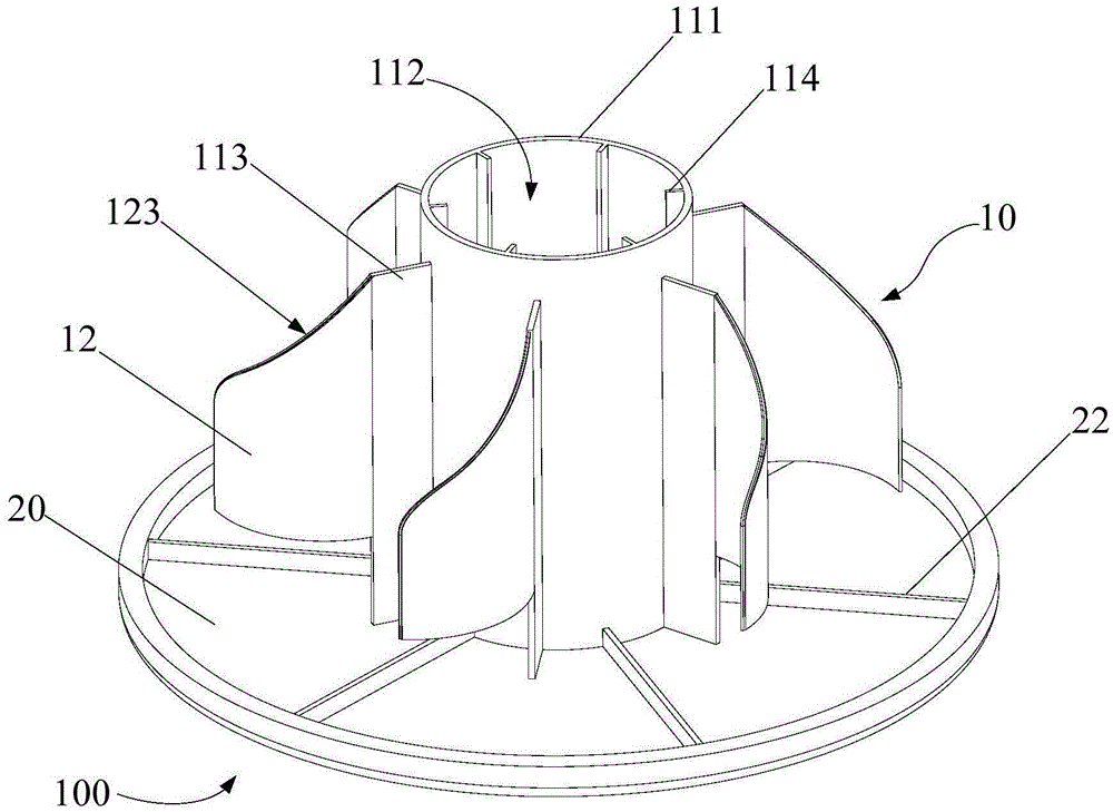
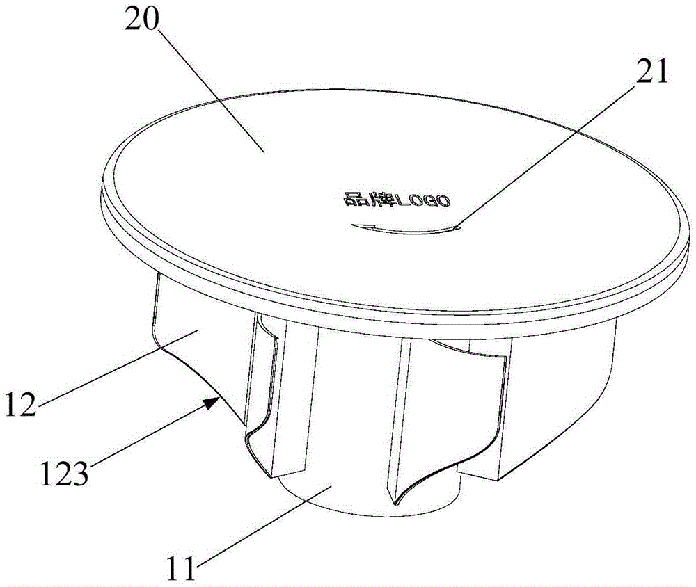
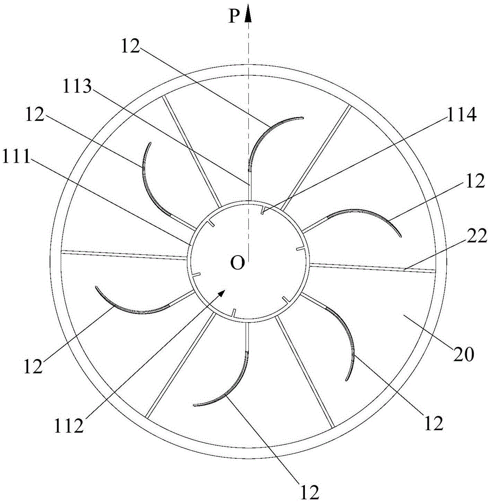
[0060] Refer below Figure 1 to Figure 8 Wall hole covers according to some embodiments of the invention are described.

[0061] Such as Figure 1 to Figure 8 As shown, the wall hole cover 100 pro...


PUM


Abstract

The invention provides a wall penetrating pipe, a wall hole cover and a wall penetrating assembly. The wall penetrating pipe is suitable for being matched with a wall hole and comprises a connecting column body and a plurality of blades arranged on the connecting column body; the blades are arranged in the circumferential direction of the side wall of the connecting column body at intervals and are arranged in a radiation manner with the connecting column body as the center; when the wall penetrating pipe is matched with the wall hole, the connecting column body is located in the wall hole, and the blades are supported between the connecting column body and the hole wall of the wall hole; and according to the wall penetrating pipe, through bending deformation of the blades supported between the hole wall of the wall hole and the connecting column body, interference fit connection between the wall penetrating pipe and the wall hole is achieved. The blades can effectively cut a space between the hole wall of the wall hole and the connecting column body, and therefore animals such as mice and birds are prevented from entering a room from the wall hole, and the wall hole blocking effect is achieved.

Description

technical field [0001] The present invention relates to the technical field of air conditioners, in particular to a wall-passing pipe, a wall hole cover with the wall-passing pipe and a wall-passing assembly including the wall hole cover. Background technique [0002] In the existing split-type air conditioner, there are evaporating pipes and condensing pipes connected between the indoor unit located in the room and the outdoor unit located outside the room. When the product is installed, it is usually necessary to open a wall hole on the wall for the evaporating pipe and condensing pipe. Tubes pass through; in response to this installation requirement, when ordinary households carry out interior decoration, they usually set up holes in the upper and lower positions of the reserved air conditioner installation position in the living room for the evaporation tube and condensation tube to pass through the wall. Specifically, The upper wall hole can be used for wall-mounted air...

Claims


Application Information

Patent Timeline
IPC IPC(8): F16L5/00
CPCF16L5/00
Inventor 朱森旺
Owner GD MIDEA AIR-CONDITIONING EQUIP CO LTD
Learn More