Device and method for identifying obstacles for rail vehicles

A technology for rail vehicles and obstacles, applied in the field of devices and methods for identifying obstacles for rail vehicles, can solve problems such as inability to accurately estimate the mass of collision objects, unintentionally initiate braking, etc., and achieve increased robustness , The effect of low manufacturing cost

Active Publication Date: 2016-11-02
SIEMENS MOBILITY AUSTRIA GMBH
View PDF6 Cites 9 Cited by
  • Summary
  • Abstract
  • Description
  • Claims
  • Application Information

AI Technical Summary

Problems solved by technology

[0004] The known system has the disadvantage of not being able to accurately estimate the mass of the colliding objects
[0005] Another disadvantage is that the vibrations that occur with increasing driving speed can lead to unintentional initiation of braking

Method used


Image

  • Device and method for identifying obstacles for rail vehicles
  • Device and method for identifying obstacles for rail vehicles
  • Device and method for identifying obstacles for rail vehicles

Examples


Embodiment Construction

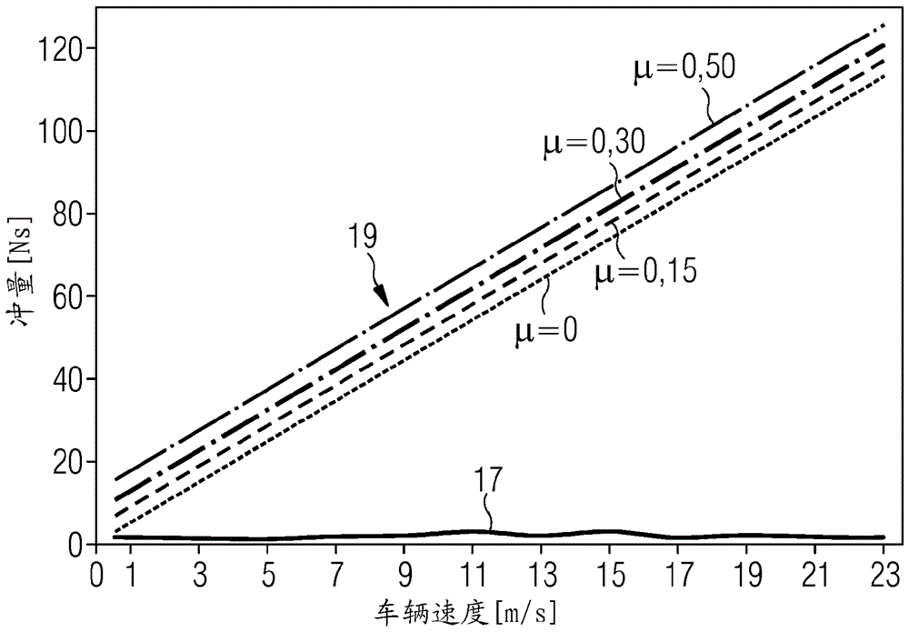
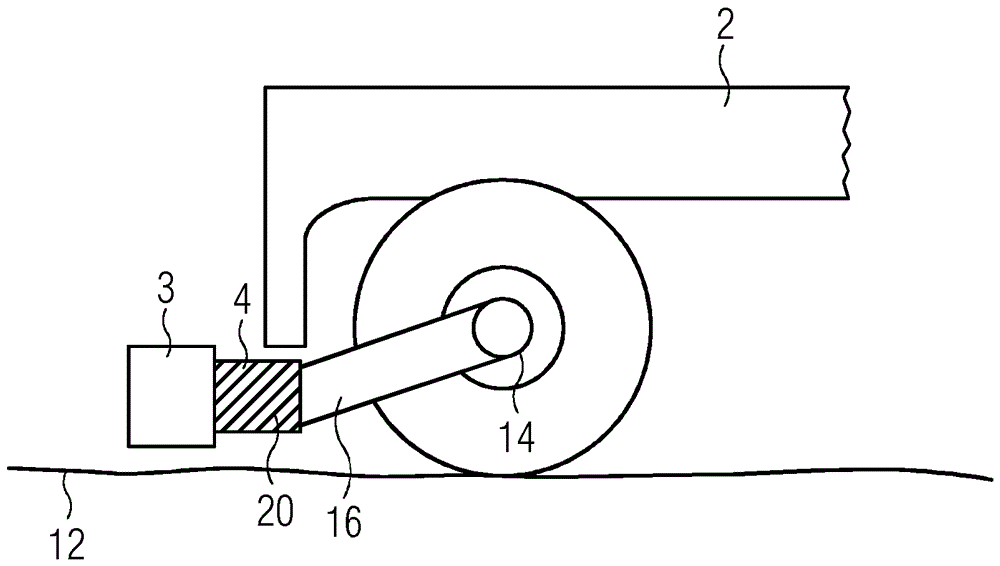
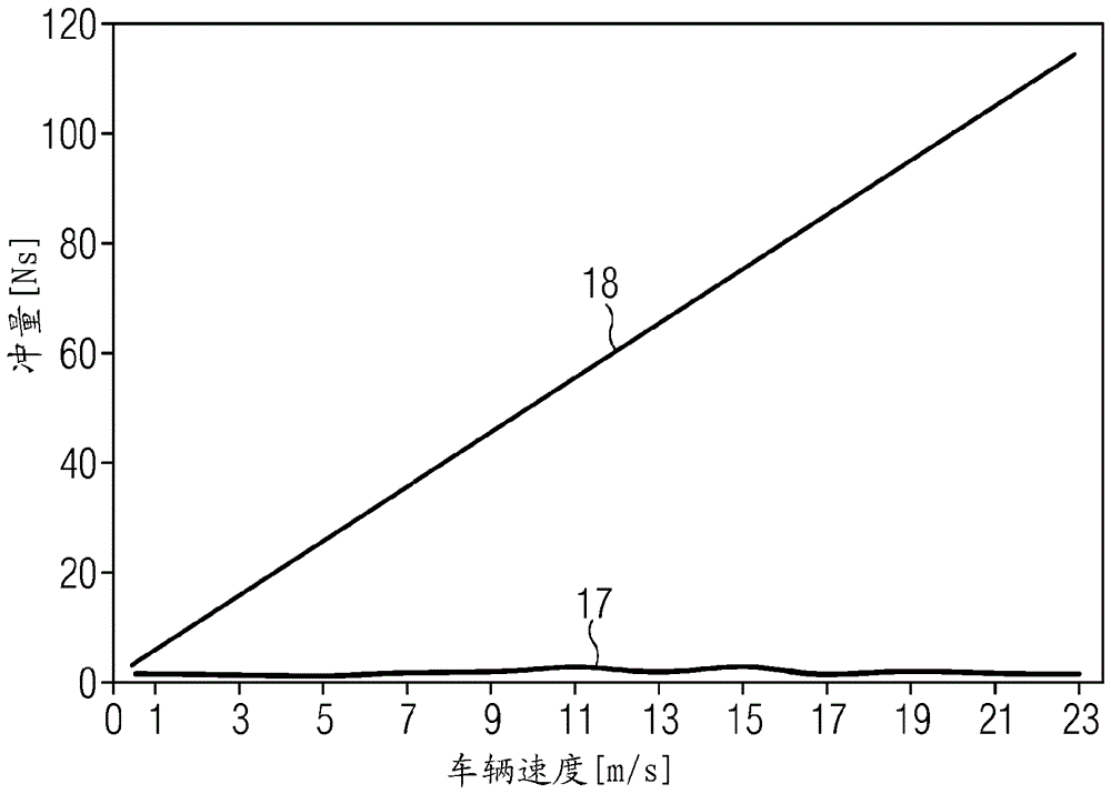
[0032] figure 1 A first exemplary embodiment of the present invention is schematically illustrated. Depend on figure 1 Indicated by reference numeral 1 in is a rail vehicle (not shown in more detail), which moves along a track 12 in the direction of arrow 10 . A rail vehicle 1 is approaching an obstacle 11 placed on a track 12 . It is assumed that the obstacle 11 is stationary and has a mass m. Located at the front of the rail vehicle 1 is a crash beam 3 , also referred to below as an obstacle deflector. If a collision occurs between the obstacle remover 3 of the rail vehicle 1 and the obstacle 11, the mass m is accelerated to at least the vehicle speed, but not more than twice the vehicle speed. The obstacle remover 3 is subjected to a collision force F. This impact force F is measured by means of a force-measuring device 4 which is arranged in the force flow between the obstacle ejector 3 and the mounting bracket 16 (mounted on the axle box 14 ). This time-dependent cr...


PUM


Abstract

The invention relates to a device for identifying obstacles for rail vehicles (1), comprising a force measuring device (4) which generates a collision force measuring signal (5) in the event of a collision between a collision beam (3) of the rail vehicle (1) and a mass (m) of the collision object (11). Said collision force measuring signal (5) is directed to an evaluation device (7) together with a rail vehicle speed signal (6) and the evaluation device (7) is designed to integrate the collision force measuring signal (5) by means of an integrator (13) and by using the rail vehicle speed signal (6), to determine the mass (m) of the collision object (11).

Description

technical field [0001] The invention relates to a device and a method for detecting obstacles for a rail vehicle comprising a force measuring device for generating a collision force measurement signal in the event of a collision between a collision beam of a rail vehicle and a collision object of a certain mass. Background technique [0002] Foreign objects on railway tracks that pose a significant hazard in the event of a collision. Accordingly, rail guards / pilots have long been used in railway systems, with which obstacles can be cleared from the railway. Such obstacle removers usually consist of a steel structure with impact beams at right angles to the direction of travel. The crash beam is fixed to the main frame or truck frame of the rail vehicle by means of mounting brackets. This type of derailer is usually positioned in front of the front wheel set and as close to the top of the rail as possible. [0003] For example, EP 2 548 783 A2 discloses a crash detection s...

Claims


Application Information

Patent Timeline
Patent Type & Authority Applications(China)
IPC IPC(8): B61L23/04
CPCB60R21/0134B61L3/008B61L23/041G08G9/02B61L23/04B61L23/00B61L25/021G01G9/00G01G19/08G01L5/0052
Inventor G.萨尔茨格贝尔
Owner SIEMENS MOBILITY AUSTRIA GMBH
Why Eureka
Try Eureka