A two-fluid spray gun

A two-fluid spray and spray gun technology, applied in the direction of liquid injection devices, spray devices, etc., can solve the problems of poor fogging performance, large water consumption, easy to block nozzle holes, etc., achieve improved fogging performance, save energy, and overcome water consumption big effect

Active Publication Date: 2018-11-16
无锡宙斯环保喷雾设备制造有限公司
View PDF10 Cites 0 Cited by
  • Summary
  • Abstract
  • Description
  • Claims
  • Application Information

AI Technical Summary

Problems solved by technology

[0004] The invention solves the disadvantages of poor fogging performance and low efficiency of the original two-fluid spray gun, and easy to block the nozzle hole when spraying urea and ammonia solution, and also overcomes the disadvantage of large water consumption in the original technology

Method used


Image

  • A two-fluid spray gun
  • A two-fluid spray gun
  • A two-fluid spray gun

Examples


Embodiment 1

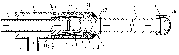
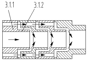
[0025] Embodiment 1: A two-fluid spray gun, comprising a cylindrical gun body 1, a liquid inlet pipe 2 arranged coaxially with the end of the gun body 1, arranged on the side wall of the cylindrical gun body 1 and communicated with the inner cavity of the cylindrical gun body 1 The air inlet pipe 1.1 of the cylindrical gun body 1 is sealed with a gas-liquid mixing joint 3 at one end of the cavity. The gas-liquid mixing joint 3 is formed by four T-shaped sleeves 3.1 which are sequentially set and sealed. The T-shaped sleeve 3.1 includes a small diameter Section 3.1.1 and large-diameter section 3.1.2, the large-diameter section 3.1.2 of the adjacent T-shaped sleeve 3.1 is socketed on the small-diameter section 3.1.1, and the central through-hole 3.1.3 of the four T-shaped sleeves 3.1 is connected to each other to form a The central mixing channel 3.2, the first T-shaped sleeve 3.1 central through hole 3.1.3 closest to the liquid inlet pipe 2 is connected to the liquid inlet pipe ...

Embodiment 2

[0026]Embodiment 2: Referring to Embodiment 1, the gas-liquid mixing joint 3 includes a base body, a central mixing channel 3.2 in the center of the base body, and the small-diameter section 3.4 of the base body extends into the cylindrical gun body 1 and is connected with the liquid inlet pipe 2. The diameter of the small-diameter section 3.4 is smaller than that of the barrel The inner diameter of the gun body is 1, and the side wall of the small diameter section 3.4 is provided with 3 dry groups of air inlet holes 3.3 inclined towards the axis of the central mixing channel 3.2. The middle section of the central mixing channel 3.2 is set as the small diameter closing section 3.2.1.

Embodiment 3

[0027] Embodiment 3: Referring to Embodiment 2, the side wall of the small-diameter section 3.4 is provided with several rectangular through grooves 3.5 around the center of the circle.

[0028] The gas-liquid mixing sleeve 7 can be added at the connection between the spray gun head 6 and the long gas-liquid mixing tube 5 in the above-mentioned embodiments 1-3, and the spiral guide body 8 is arranged inside the gas-liquid mixing sleeve 7 .

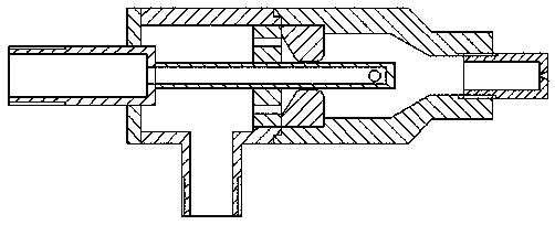
[0029] The gas-liquid mixing long tube 5 is actually an oblong channel, which is a cavity for the gas-liquid to roll, rotate and impact the flow in the cavity, which is different from the original technology ( figure 1 ) ratio, the length of the mixing chamber has increased a lot, from the original 40~50mm to 500~800mm. The purpose of the increase of the gas-liquid mixing chamber is to allow enough time and space for gas and liquid to mix in the chamber to improve the mixing effect. The basis for determining the length of the mixing chambe...


PUM


Abstract

A two-fluid spray gun comprises a two-fluid spray gun which comprises a cylindrical gun body, a liquid inlet pipe coaxially arranged with the tail end of the gun body, and an air inlet pipe being arranged on the side wall of the cylindrical gun body and communicating with the inner cavity of the cylindrical gun, wherein an air-liquid mixing connector is arranged at one end of the inner cavity of the cylindrical gun body in a sealing manner; a cut-through central mixing channel is formed in the center of the air-liquid mixing connector; the liquid inlet pipe extends into the cylindrical gun body and communicates with one end of the central mixing channel of the gas-liquid mixing connector; the other end of the central mixing channel of the gas-liquid mixing connector is connected with an air-liquid mixing long pipe; the end part of the air-liquid mixing long pipe is connected with a spray gun head; an air inlet channel is formed in a cavity between the inner wall of the cylindrical gun body and the liquid inlet pipe; and air inlet holes used for connecting the central mixing channel with the inner cavity of the cylindrical gun body are formed in the side wall of the air-liquid mixing connector. The two-fluid spray gun is high in flow rate, large in spray hole, good in atomizing property and resistant to blockage.

Description

technical field [0001] The invention discloses a double-fluid spray spray gun used for denitrification and desulfurization systems of coal-fired boilers and kilns for flue cooling and dust removal, and belongs to the environmental protection machinery industry. Background technique [0002] In the industrial field, the waste gas containing nitrate and sulfur produced by coal-fired and gas-fired furnaces in power plants, smelters, and cement plants must undergo environmental protection treatment to meet the national emission standards. The denitrification method generally uses catalytic absorbents such as urea and ammonia. Dissolve in water, spray and wash the exhaust gas with a spray gun through the method of water-air mixed spraying, so as to achieve the purpose. Therefore, the fogging performance of the spray gun directly affects the effect of denitrification and desulfurization, and is also related to the water consumption and the operation cost of the equipment. The spr...

Claims


Application Information

Patent Timeline
Patent Type & Authority Patents(China)
IPC IPC(8): B05B7/04B05B15/00
CPCB05B7/04B05B7/0416B05B15/00
Inventor 堵杰兴徐浩文徐国明钱志鹏蒋龙福
Owner 无锡宙斯环保喷雾设备制造有限公司
Why Eureka
Try Eureka