Clamping device of molds of engraving-milling machines

A kind of engraving and milling machine and clamping technology, which is applied in the direction of positioning device, clamping, manufacturing tools, etc., can solve the problems of laborious mold fixing, damaged mold, mold stability cannot be guaranteed, etc., and achieve the effect of stable clamping

Inactive Publication Date: 2016-11-09
安徽龙锐模塑有限公司
View PDF4 Cites 4 Cited by
  • Summary
  • Abstract
  • Description
  • Claims
  • Application Information

AI Technical Summary

Problems solved by technology

[0002] The clamping device of the traditional engraving and milling machine is to manually install the mold on the clamping device. Since the stability of the mold is very important in the process of engraving and milling, the stability of the mold cannot be guaranteed by manual force. Therefore, workers need to work hard to fix the mold on the mounting device, and sometimes the mold will be damaged if too much force is used. The traditional clamping mechanism can only clamp a specific shape of engraving and milling products. When changing the shape of engraving and milling products, It is very troublesome to replace and replace the clamping device

Method used


Image

  • Clamping device of molds of engraving-milling machines
  • Clamping device of molds of engraving-milling machines
  • Clamping device of molds of engraving-milling machines

Examples


Embodiment Construction

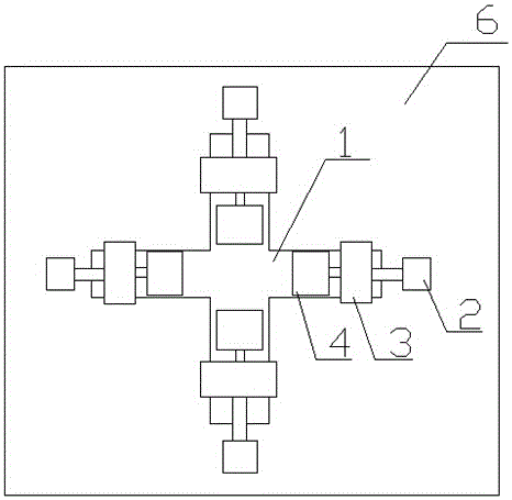
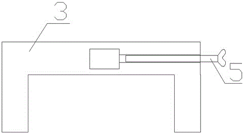
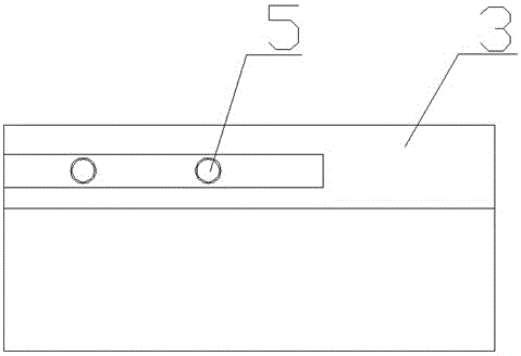
[0015] Such as figure 1 As shown, the present invention discloses a clamping device for engraving and milling machine molds, comprising: slide rail 1, cylinder 2, slider 3, splint 4, butterfly screw 5, machine tool 6, and the slide rail 1 is welded on 6 on the machine tool, the slide rail 1 is provided with four identical clamping groups, the clamping group includes: slide rail 1, cylinder 2, slider 3, splint 4, and the cylinder 2 is connected by bolts On the machine tool, and the cylinder 2 is at the right end of the slide rail 1, the slide frame on the slide rail 1 is provided with a slide block 3, and the slide block 3 is a U-shaped slide block 3, and the slide block 3 is connected to the cylinder 2 by bolts. The piston rod is connected, the left end of the slider 3 is connected to a splint 4 through a butterfly screw 5, and the splint 4 is on the upper surface of the slide rail 1.

[0016] The slider 3 is clamped on the slide rail 1 by the U-shaped side wall of the slider...


PUM


Abstract

The invention discloses a clamping device of molds of engraving-milling machines. The clamping device comprises sliding rails, air cylinders, sliding blocks, clamping plates, butterfly-shaped screws and a machine tool, wherein the sliding rails are welded to the machine tool; the sliding rails are provided with four uniform clamping sets, each clamping set comprises one sliding rail, one air cylinder, one sliding block and one clamping plate, the air cylinders are arranged on the machine tool through bolts and are located at the right ends of the sliding rails, the sliding blocks are erected on the sliding rails in a sliding mode, are respectively of a U shape and are connected to piston rods of the air cylinders through bolts, the left end of each sliding block is connected to one clamping plate through one butterfly-shaped screw, and the clamping plates are arranged on the upper surfaces of the sliding rails. The clamping device has the advantages that time and labor are saved and clamping is stable and firm.

Description

technical field [0001] The invention relates to a clamping device, in particular to a clamping device for an engraving and milling machine mold. Background technique [0002] The clamping device of the traditional engraving and milling machine is to manually install the mold on the clamping device. Since the stability of the mold is very important in the process of engraving and milling, the stability of the mold cannot be guaranteed by manual force. Therefore, workers need to work hard to fix the mold on the mounting device, and sometimes the mold will be damaged if too much force is used. The traditional clamping mechanism can only clamp a specific shape of engraving and milling products. When changing the shape of engraving and milling products, It is very troublesome to replace and replace the clamping device. Contents of the invention [0003] In order to solve the defects of the existing technical solutions, the invention discloses a clamping device for engraving an...

Claims


Application Information

Patent Timeline
Patent Type & Authority Applications(China)
IPC IPC(8): B23Q3/08
CPCB23Q3/08
Inventor 成龙武
Owner 安徽龙锐模塑有限公司
Why Eureka
Try Eureka