Firmly-clamping lever-type clamping device

A lever-type, clamping technology, which is applied to other household appliances, household components, household appliances, etc., can solve the problems of easy loosening and falling, poor clamping reliability, etc., and achieve clamping locking safety and firm clamping Effect

Pending Publication Date: 2021-03-05
彭志军
View PDF0 Cites 0 Cited by
  • Summary
  • Abstract
  • Description
  • Claims
  • Application Information

AI Technical Summary

Problems solved by technology

The main deficiency of this clamping seat is: the desk lamp or the fan are fixed only by the elastic force applied by the torsion spring, when the desk lamp or the fan volume is slightly larger, or the desk lamp or the fan is fixed on a moving object and used (such as a train or on a car), it is very poorly clamped, and it is easy to loosen and fall

Method used


Image

  • Firmly-clamping lever-type clamping device
  • Firmly-clamping lever-type clamping device
  • Firmly-clamping lever-type clamping device

Examples


Embodiment 1

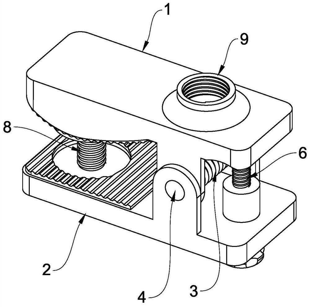
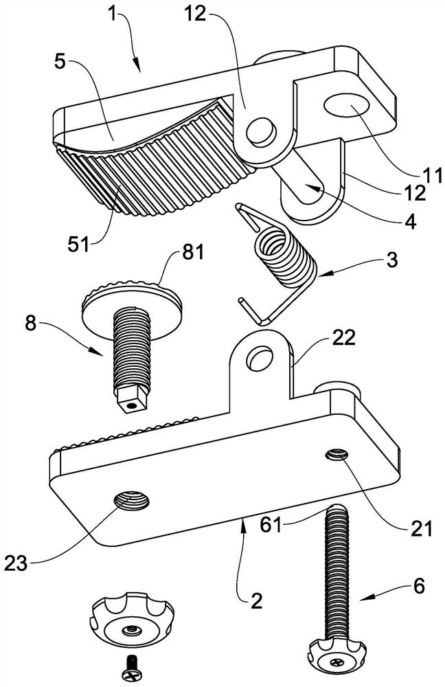
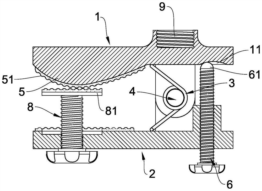
[0021] like Figure 1 to Figure 6 As shown, a lever-type clamping device with reliable clamping according to the present invention includes a first clamping part 1, a second clamping part 2, an elastic part 3 and a pin shaft 4, and the first clamping part 1 and the second clamping part 2 are hingedly assembled together through a pin 4 , and the elastic part 3 is arranged between the first clamping part 1 and the second clamping part 2 . In order to realize the purpose that the present invention proposes, as figure 1 and figure 2 As shown, the present invention also includes a tightening bolt 6, and one end of the second clamping part 2 is provided with a screw hole 21 for screwing the tightening bolt 6, and the tightening bolt 6 is screwed into the screw hole 21 Among them, on the inner surface of one end of the first clamping component 1, there is correspondingly provided a concave position 11 for the jacking bolt 6 to rest on.

[0022] like figure 2 As shown, the inner...

Embodiment 2

[0030] The specific structure of this second embodiment is slightly different from that of the previous embodiment one. This difference is mainly reflected in the specific structure of the first clamping part 1 and the second clamping part 2. Other aspects are basically the same, and The technical effect and purpose it obtains are also the same. The concrete scheme structure of present embodiment two is like this: as Figure 7 to Figure 12 As shown, it also includes a first clamping part 1 and a second clamping part 2, an elastic part 3 and a pin shaft 4, and the first clamping part 1 and the second clamping part 2 are hingedly assembled to each other through the pin shaft 4 Together, the elastic member 3 is disposed between the first clamping component 1 and the second clamping component 2—a common technical feature of the like. The difference feature of the second embodiment is specifically as follows: Figure 8 As shown, the front end of the first clamping part 1 is provi...


PUM


Abstract

The invention relates to a firmly-clamping lever-type clamping device which comprises a first clamping component, a second clamping component, an elastic component, a pin shaft and a puller bolt. Thefirst clamping component and the second clamping component are assembled in a hinged mode, and the elastic component is arranged between the first clamping component and the second clamping component.One end of the second clamping component is provided with a screw hole for screwing the puller bolt, and the puller bolt is screwed in the screw hole. The inner side face of one end of the first clamping component is further correspondingly provided with a concave position for the puller bolt to abut against, the inner side face of the other end of the first clamping component is further providedwith an arc-shaped protruding part, the surface of the arc-shaped protruding part is further provided with insection, and the puller bolt abuts against the concave position. The clamping device is firm and reliable in clamping, does not loosen, is very safe in clamping and locking, and can carry out clamping and does not loosen even if the clamping device clamps a moving or vibrating object.

Description

technical field [0001] The invention relates to the field of desk lamps or fans, in particular to a clamping device for desk lamps or fans. Background technique [0002] At present, the common clip-mounted desk lamp or fan used for fixed use usually has a clip-mounted seat consisting of an upper half clip part, a lower half clip part, a pin shaft, and a torsion spring. When clamping, overcome the elastic force of the torsion spring, so that the upper half of the clamping part and the lower half of the clamping part are relatively opened, and use the elastic force of the torsion spring to clamp on the edge of the table or other objects, so that the desk lamp or fan is fixed in a clamping manner Use it on a table or other object. The main deficiency of this clamping seat is: the desk lamp or the fan are fixed only by the elastic force applied by the torsion spring, when the desk lamp or the fan volume is slightly larger, or the desk lamp or the fan is fixed on a moving object...

Claims


Application Information

Patent Timeline
Patent Type & Authority Applications(China)
IPC IPC(8): A47G29/087
CPCA47G29/087
Inventor 彭志军
Owner 彭志军
Why Eureka
Try Eureka