Pouring mold and pouring using method for plate type concrete steel bar positioning blocks

A technology for concrete reinforcement and pouring molds, which is used in auxiliary mold parts, manufacturing tools, ceramic molding machines, etc., can solve problems affecting concrete performance and apparent quality, reinforced concrete strength deviation, and template distance changes.

Inactive Publication Date: 2016-11-09
IANGSU COLLEGE OF ENG & TECH
View PDF5 Cites 7 Cited by
  • Summary
  • Abstract
  • Description
  • Claims
  • Application Information

AI Technical Summary

Problems solved by technology

[0002] In current construction projects, components that need to be poured with slab concrete are often encountered. In the existing concrete pouring, criss-cross steel frame structures must be added to strengthen the stability of the pouring. However, when pouring this structure There is a certain standard distance between the steel frame and the formwork of the slab concrete to ensure the strength of the poured reinforced concrete. In actual operation, the steel frame will be displaced during the pouring process due to the instability of the steel frame before pouring. , so that the distance from the formwork changes, resulting in a deviation in the strength of the poured reinforced concrete
[0003] In view of this situation, the most common way is to cut the steel bars with standard distances, and weld these steel bar segments on the steel frame. When pouring, the steel bars will be poured inside the concrete. After the steel plate is removed, the ends of the steel bars will be exposed outside. With the long-term wind and rain, the steel bars will rust, which will affect the performance and apparent quality of the concrete.
[0004] Aiming at the shortcomings of the steel bars, there is a ready-made positioning pad on the market. This positioning pad is usually made of plastic material, directly fixed on the steel bar by tying wires, and poured inside together with the concrete during pouring. Although this positioning pad The block will not be rusted by rain in the later use, which will affect the performance of the concrete, but its material and color are quite different from the concrete. After the formwork is removed, the exposed block and the concrete have obvious color differences, which will affect the overall structure. It is beautiful, and at the same time, the pad is directly fixed to the steel bar through wire binding, and there is displacement, resulting in inaccurate positioning

Method used


Image

  • Pouring mold and pouring using method for plate type concrete steel bar positioning blocks
  • Pouring mold and pouring using method for plate type concrete steel bar positioning blocks
  • Pouring mold and pouring using method for plate type concrete steel bar positioning blocks

Examples


Embodiment Construction

[0025] The technical solutions of the embodiments of the present invention will be clearly and completely described below in conjunction with the accompanying drawings of the present invention.

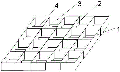
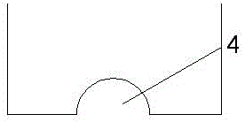
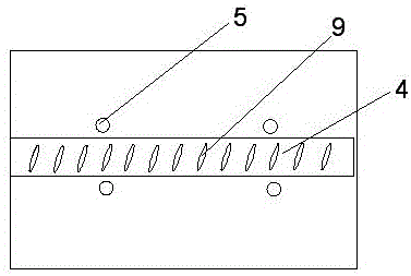
[0026] like Figure 1~4 As shown, a casting mold of a slab concrete reinforcement positioning block disclosed by the present invention is used for pouring a slab concrete reinforcement positioning block. The mold 1 is a cubic structure, and its interior is a cubic cavity. A plurality of criss-cross partitions 2 are provided to divide the cavity into a plurality of pouring troughs 3 of the same size, and the bottom surface of the pouring trough 3 is provided with a semi-cylindrical raised block 4 transversely, and the two sides of the raised block 4 A plurality of round holes 5 are arranged on the bottom surface of the raised block, and transverse convex ribs 9 are evenly distributed on the upper surface of the raised block, which are the same as the spacing and size of the transverse ...


PUM

PropertyMeasurementUnit
lengthaaaaaaaaaa
radiusaaaaaaaaaa
particle diameteraaaaaaaaaa

Abstract

The invention discloses a pouring mold for plate type concrete steel bar positioning blocks. The pouring mold is used for pouring the positioning blocks for plate type concrete steel bars and is of a cubic structure, a cubic cavity is formed in the pouring mold, multiple crisscross partition plates are arranged in the cavity to divide the cavity into multiple pouring grooves with the same size, the bottom face of each pouring groove is transversely provided with a semi-cylindrical convex block, and the bottom faces of the two sides of each convex block are provided with multiple circular holes. According to the pouring mold for the plate type concrete steel bar positioning blocks, the positioning blocks for positioning the steel bars in plate type concrete are poured through the mold, the positioning blocks can be attached and fixed to the steel bars, the color and material of the positioning blocks are same as those of the concrete, and therefore attractiveness and stability which are achieved after mold plates are disassembled are not affected.

Description

technical field [0001] The invention belongs to the field of building accessories, in particular to a pouring mold for a plate-type concrete reinforcement positioning block. Background technique [0002] In current construction projects, components that need to be poured with slab concrete are often encountered. In the existing concrete pouring, criss-cross steel frame structures must be added to strengthen the stability of the pouring. However, when pouring this structure There is a certain standard distance between the steel frame and the formwork of the slab concrete to ensure the strength of the poured reinforced concrete. In actual operation, the steel frame will be displaced during the pouring process due to the instability of the steel frame before pouring. , so that the distance from the formwork changes, resulting in a deviation in the strength of the poured reinforced concrete. [0003] In view of this situation, the most common way is to cut the steel bars with s...

Claims


Application Information

Patent Timeline
Patent Type & Authority Applications(China)
IPC IPC(8): B28B7/24B28B7/00B28B1/087B28B1/29B28B23/02B28B1/04E04C5/20
CPCB28B7/243B28B1/045B28B1/0873B28B1/29B28B7/0002B28B23/02E04C5/20
Inventor 杨化奎
Owner IANGSU COLLEGE OF ENG & TECH
Why Eureka
Try Eureka