Device for automatically transferring products to rack

A product and material rack technology, which is applied in the field of automatic product transfer material rack devices, can solve the problems of easy scratches, time-consuming, and laborious products

Active Publication Date: 2016-11-09
EELY ECW TECH
View PDF9 Cites 22 Cited by
  • Summary
  • Abstract
  • Description
  • Claims
  • Application Information

AI Technical Summary

Problems solved by technology

[0004] The present invention provides an automatic lifting mechanism and a device for automatically transferring product racks to replace the manual operation to transfer products between different racks, and solve the time-consuming, laborious, and easy-to-scratch problems of manual operations. Injuries and other issues

Method used


Image

  • Device for automatically transferring products to rack
  • Device for automatically transferring products to rack
  • Device for automatically transferring products to rack

Examples


Embodiment 1

[0076] This embodiment provides a device for automatically transferring product racks, including an automatic lifting mechanism and an automatic rack insertion mechanism, and the device for automatically transferring product racks also includes a first The manipulator, the material tray stacked in the automatic lifting mechanism, and the conveying positioning mechanism, the second manipulator and the material rack independently arranged on the automatic rack insertion mechanism, the device for automatically transferring the material rack It also includes a working drive mechanism electrically connected to the automatic lifting mechanism, the first manipulator, the conveying positioning mechanism, the second manipulator, and the material rack, wherein:

[0077] The automatic lifting mechanism is used to lift the tray containing the product to the first designated position according to the first preset trajectory under the drive of the working driving mechanism; the first manipul...

Embodiment 2

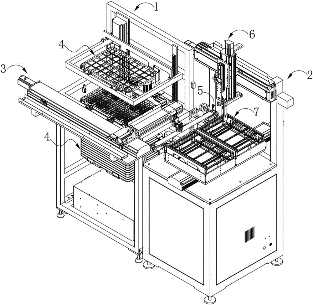
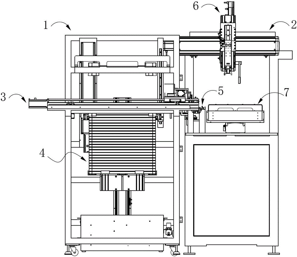
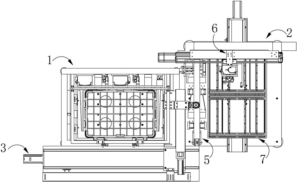
[0079] This embodiment provides a device for automatic transfer of product racks, combined with Figure 1 to Figure 4As shown, the device for automatic product rack transfer includes an automatic lifting mechanism 1 and an automatic rack insertion mechanism 2 located on the right side of the automatic lifting mechanism 1 . A first manipulator 3 and a material tray 4 are respectively provided in the automatic lifting mechanism 1 , and a delivery positioning mechanism 5 , a second manipulator 6 and a material rack 7 are respectively independently provided on the automatic rack insertion mechanism 2 . The device for automatically transferring the product rack also includes a working drive mechanism electrically connected to the automatic lifting mechanism 1, the automatic rack insertion mechanism 2, the first manipulator 3, the conveying positioning mechanism 5, and the second manipulator 6 (not shown in the figure). ).

[0080] Among them, the automatic lifting mechanism 1 is u...

Embodiment 3

[0107] The difference between this embodiment and the second embodiment is only that the structure of the one-way supporting member is different, specifically: the magnets are no longer embedded in the inner surface of the supporting block and the surface of the accommodating groove, but in the inner surface of the supporting block. A recoverable deformable spring is arranged between the surface and the surface of the accommodating groove, so that the supporting block and the accommodating groove are elastically connected. When there is no external pressure, due to the elasticity of the spring, the supporting block protrudes outward from the accommodating groove. At this time, the supporting surface of the supporting block is upward and can support the material tray located above it. When the external pressure is greater than the elastic force between the supporting block and the accommodating groove, the supporting block is accommodated in the accommodating groove, and the out...


PUM


Abstract

The invention provides a device for automatically transferring products to a rack. The device comprises an automatic lifting mechanism and an automatic rack inserting mechanism and further comprises a first mechanical arm arranged on the automatic lifting mechanism, trays arranged in the automatic lifting mechanism in a stacked mode, a conveying positioning mechanism, a second mechanical arm and the rack, wherein the conveying positioning mechanism, the second mechanical arm and the rack are arranged on the automatic rack inserting mechanism independently. The device further comprises a work drive mechanism electrically connected with the automatic lifting mechanism, the automatic rack inserting mechanism, the first mechanical arm, the conveying positioning mechanism and the second mechanical arm. Under the drive of the work drive mechanism, the automatic lifting mechanism jacks the trays carrying the products to a first designated position, the first mechanical arm transfers the products on the trays to the front end of the conveying positioning mechanism at the position, then the products are conveyed to the rear end of the conveying positioning mechanism through the conveying positioning mechanism, finally, the second mechanical arm inserts the products into the rack. By means of the device, automatic transfer of the products between the corresponding tray and the rack in different directions can be achieved, and the functions of improving production efficiency and lowering the manual operation risk are achieved.

Description

technical field [0001] The invention relates to the field of mechanical devices, in particular to a device for automatic product transfer racks. Background technique [0002] In touch screen panel processing technology, trays and racks are often used to place products to be processed or processed. Wherein, the space in the material tray is generally a horizontal accommodation space, so that the touch screen panel can be placed horizontally therein; the space in the material rack is generally a vertical accommodation space, so that the touch screen panel can be placed vertically therein. When the touch screen panel needs to be transferred between the material tray and the material rack, it is usually manually operated, that is, the touch screen panel in the material tray is manually taken out and then inserted into the material rack. [0003] However, in large-scale industrial production, the number of touch screen panels produced in batches is very large, which requires man...

Claims


Application Information

Patent Timeline
Patent Type & Authority Applications(China)
IPC IPC(8): B65G49/06
CPCB65G49/06B65G49/061B65G49/063B65G49/067
Inventor 张义
Owner EELY ECW TECH
Why Eureka
Try Eureka