Device for automatic product transfer rack
A product and material rack technology, which is applied in the field of automatic product transfer material rack devices, can solve problems such as laborious, time-consuming, and easily scratched products
- Summary
- Abstract
- Description
- Claims
- Application Information
AI Technical Summary
Problems solved by technology
Method used
Image
Examples
Embodiment 1
[0076] This embodiment provides a device for automatically transferring product racks, including an automatic lifting mechanism and an automatic rack insertion mechanism, and the device for automatically transferring product racks also includes a first The manipulator, the material tray stacked in the automatic lifting mechanism, and the conveying positioning mechanism, the second manipulator and the material rack independently arranged on the automatic rack insertion mechanism, the device for automatically transferring the material rack It also includes a working drive mechanism electrically connected to the automatic lifting mechanism, the first manipulator, the conveying positioning mechanism, the second manipulator, and the material rack, wherein:
[0077] The automatic lifting mechanism is used to lift the tray containing the product to the first designated position according to the first preset trajectory under the drive of the working driving mechanism; the first manipul...
Embodiment 2
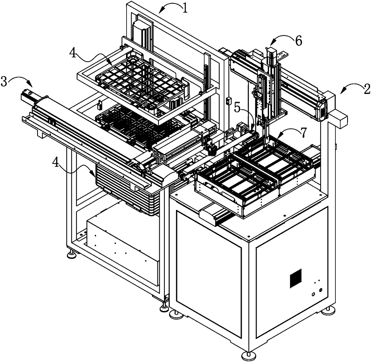
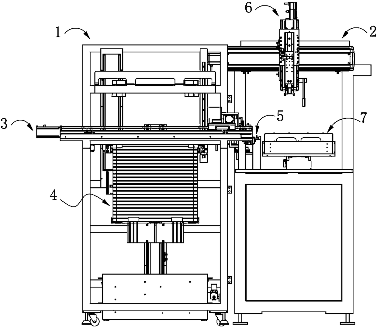
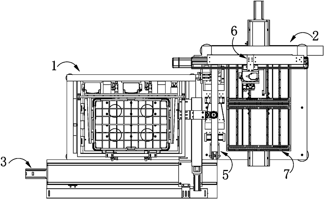
[0079] This embodiment provides a device for automatic transfer of product racks, combined with Figure 1 to Figure 4As shown, the device for automatic product rack transfer includes an automatic lifting mechanism 1 and an automatic rack insertion mechanism 2 located on the right side of the automatic lifting mechanism 1 . A first manipulator 3 and a material tray 4 are respectively provided in the automatic lifting mechanism 1 , and a delivery positioning mechanism 5 , a second manipulator 6 and a material rack 7 are respectively independently provided on the automatic rack insertion mechanism 2 . The device for automatically transferring the product rack also includes a working drive mechanism electrically connected to the automatic lifting mechanism 1, the automatic rack insertion mechanism 2, the first manipulator 3, the conveying positioning mechanism 5, and the second manipulator 6 (not shown in the figure). ).
[0080] Among them, the automatic lifting mechanism 1 is u...
Embodiment 3
[0107] The difference between this embodiment and the second embodiment is only that the structure of the one-way supporting member is different, specifically: the magnets are no longer embedded in the inner surface of the supporting block and the surface of the accommodating groove, but in the inner surface of the supporting block. A recoverable deformable spring is arranged between the surface and the surface of the accommodating groove, so that the supporting block and the accommodating groove are elastically connected. When there is no external pressure, due to the elasticity of the spring, the supporting block protrudes outward from the accommodating groove. At this time, the supporting surface of the supporting block is upward and can support the material tray located above it. When the external pressure is greater than the elastic force between the supporting block and the accommodating groove, the supporting block is accommodated in the accommodating groove, and the out...
PUM
 Abstract
Description
Claims
Application Information
 - R&D
- Intellectual Property
- Life Sciences
- Materials
- Tech Scout
- Unparalleled Data Quality
- Higher Quality Content
- 60% Fewer Hallucinations
Browse by: Latest US Patents, China's latest patents, Technical Efficacy Thesaurus, Application Domain, Technology Topic, Popular Technical Reports.
© 2025 PatSnap. All rights reserved.Legal|Privacy policy|Modern Slavery Act Transparency Statement|Sitemap|About US| Contact US: help@patsnap.com


