Shearing machine blanking magnetic buffer

A technology of shearing machine and buffer, which is applied in the direction of object stacking, transportation and packaging, etc. It can solve the problems of long time for the plate to leave the conveyor belt, long protruding distance of the front end of the plate, and inability to support the plate, etc., to achieve convenient installation, The effect of reducing production costs and facilitating installation and adjustment

Active Publication Date: 2018-03-27
成都宝钢汽车钢材部件加工配送有限公司
View PDF6 Cites 0 Cited by
  • Summary
  • Abstract
  • Description
  • Claims
  • Application Information

AI Technical Summary

Problems solved by technology

[0003] However, when producing longer boards, the time it takes for the boards to leave the conveyor belt is longer. Scratches on the upper surface of the sheet

Method used


Image

  • Shearing machine blanking magnetic buffer
  • Shearing machine blanking magnetic buffer
  • Shearing machine blanking magnetic buffer

Examples


Embodiment Construction

[0029] In order to make the object, technical solution and advantages of the present invention clearer, the present invention will be further described in detail below in conjunction with the accompanying drawings.

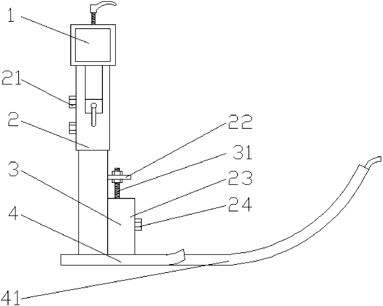
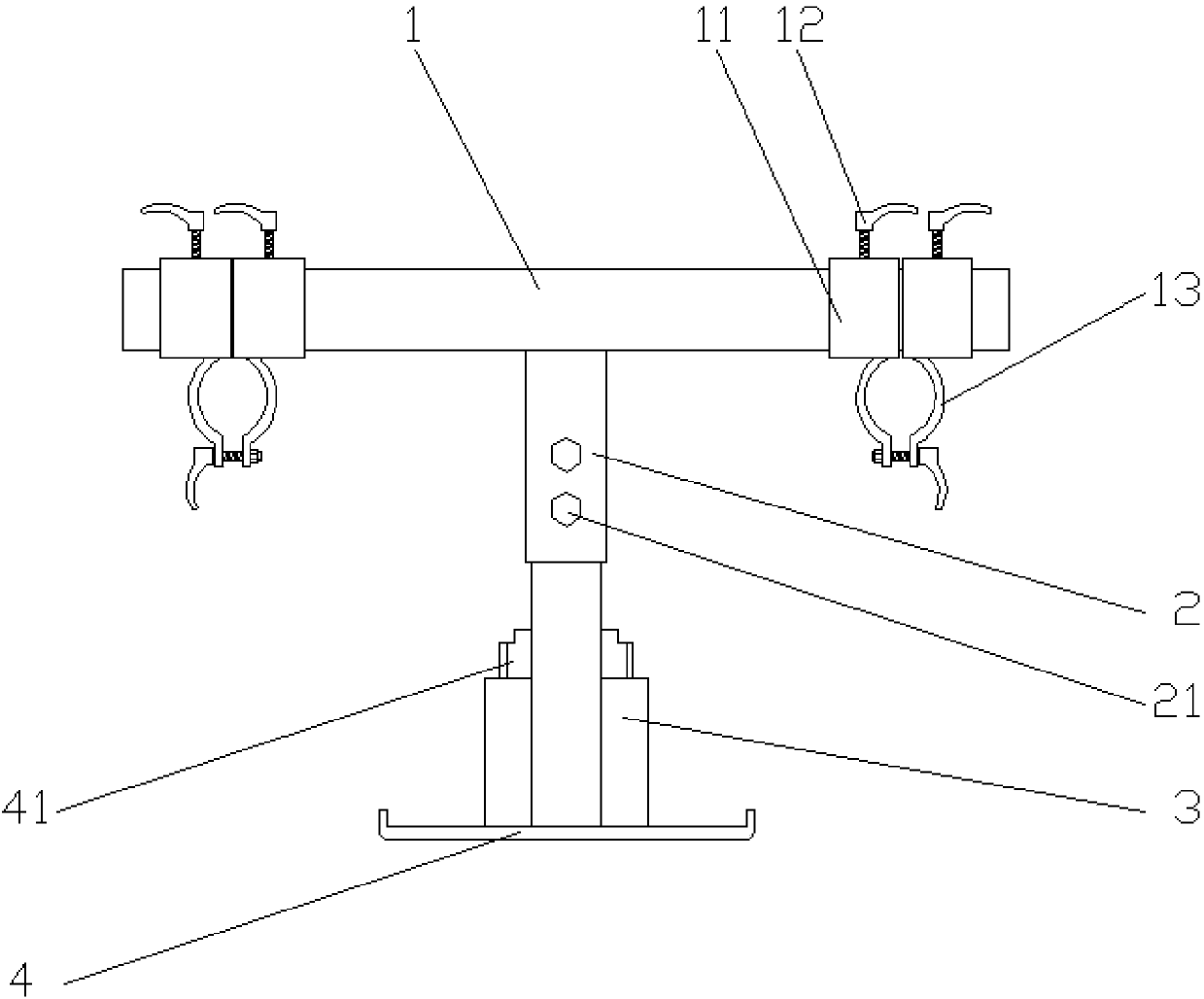
[0030] like figure 1 , 2 As shown, the blanking magnetic buffer of the shearing machine disclosed by the present invention includes a column 2, a permanent magnet 3, and a baffle 4. The baffle 4 is installed on the rear side of the conveyor belt of the shearing machine, and the lower surface of the baffle 4 is higher than the upper surface of the conveyor belt. , the distance between the lower surface of the baffle plate 4 and the upper surface of the conveyor belt is the thickness of the cutting plate, the permanent magnet 3 is installed above the baffle plate 4, the bottom surface of the column 2 is connected with the upper surface of the baffle plate 4, and the side wall of the column 2 is provided with a horizontal mounting plate 22, the mounting plate 22 is ...


PUM


Abstract

The invention discloses a blanking magnetic buffer of a plate shearing machine, and belongs to the field of plate production machines. The blanking magnetic buffer comprises a permanent magnet and a baffle. The baffle is mounted on the rear side of a conveying belt of the plate shearing machine. The lower surface of the baffle is higher than the upper surface of the conveying belt. The distance between the lower surface of the baffle and the upper surface of the conveying belt is the thickness of a shorn plate. The permanent magnet is mounted above the baffle. According to the blanking magnetic buffer, no power source is needed, fixed mounting and adjusting are facilitated, and the blanking magnetic buffer can be suitable for production of long plates.

Description

technical field [0001] The invention relates to a plate production equipment, in particular to a blanking magnetic buffer of a shearing machine. Background technique [0002] To produce sheet metal, the tape needs to be uncoiled, flattened, cut and stacked. In the automatic production line, the cut plates are transported by the conveyor belt and finally stacked together. However, when the plate is separated from the conveyor belt, due to the effect of gravity, the front end of the plate will fall first, which will scratch the upper surface of the lower plate. In order to avoid this kind of defect, the air blowing method is adopted at this stage. A blowing port is set under the end of the conveyor belt, and the board is blown by the wind force to prevent the front end of the board from falling first. [0003] However, when producing longer boards, the time it takes for the boards to leave the conveyor belt is longer. The upper surface of the sheet is scratched. Contents ...

Claims


Application Information

Patent Timeline
Patent Type & Authority Patents(China)
IPC IPC(8): B65G57/11
CPCB65G57/11
Inventor 杨波
Owner 成都宝钢汽车钢材部件加工配送有限公司
Why Eureka
Try Eureka