
Automatic bending and wire-wrapping machine for mutual inductor copper skin

A technology of transformers and wrapping machines, which is applied in the manufacture of inductors/transformers/magnets, feeding devices, positioning devices, etc., and can solve problems such as cumbersome operations, time-consuming and labor-intensive, and low efficiency

Inactive Publication Date: 2021-01-29
刘琼
View PDF0 Cites 0 Cited by
  • Summary
  • Abstract
  • Description
  • Claims
  • Application Information

AI Technical Summary

Problems solved by technology

[0003] as attached Figure 9-11 As shown, at present, the bending of copper skin is performed manually by a person. First, the rolled copper skin is automatically cut into copper skins of the required size, and then the two sides of the copper skin are manually bent in the length direction using a jig. Then place the lead wire in the bent part, then flatten the bent part, wrap the lead wire in the bent part of the copper skin, play the role of grounding or connecting with other components, so as to facilitate the subsequent processing of the transformer and realize automatic production; One person can only bend about 100 pieces per day. The copper sheet is a whole roll. It is first cut into the required size and then processed. The operation is cumbersome, the efficiency is low, time-consuming and labor-intensive. In order to improve efficiency, a copper sheet needs to be customized. Automated bending equipment to solve the above technical problems

Method used


Image

  • Automatic bending and wire-wrapping machine for mutual inductor copper skin
  • Automatic bending and wire-wrapping machine for mutual inductor copper skin
  • Automatic bending and wire-wrapping machine for mutual inductor copper skin

Examples


Embodiment Construction

[0032] The technical solutions of the present invention will be clearly and completely described below in conjunction with the accompanying drawings. Apparently, the described embodiments are some of the embodiments of the present invention, but not all of them.

[0033] The components of the embodiments of the invention generally described and shown in the figures herein may be arranged and designed in a variety of different configurations. Accordingly, the following detailed description of the embodiments of the invention provided in the accompanying drawings is not intended to limit the scope of the claimed invention, but merely represents selected embodiments of the invention.

[0034] Based on the embodiments of the present invention, all other embodiments obtained by persons of ordinary skill in the art without making creative efforts belong to the protection scope of the present invention.

[0035] In the description of the present invention, it should be noted that the...


PUM


Abstract

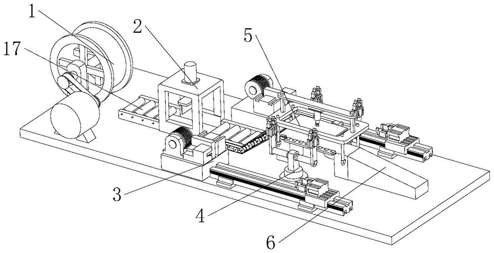
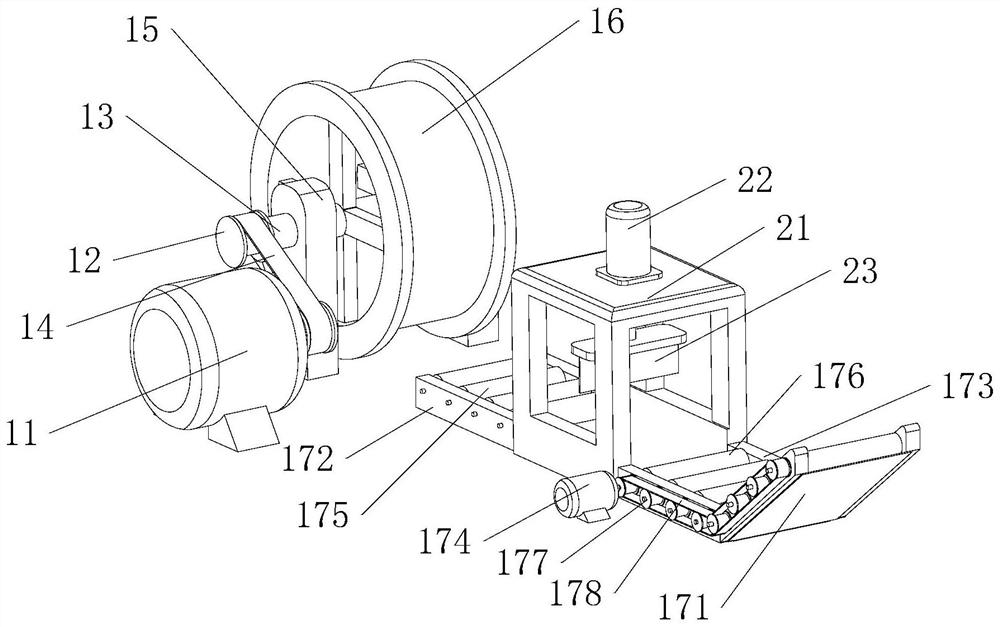
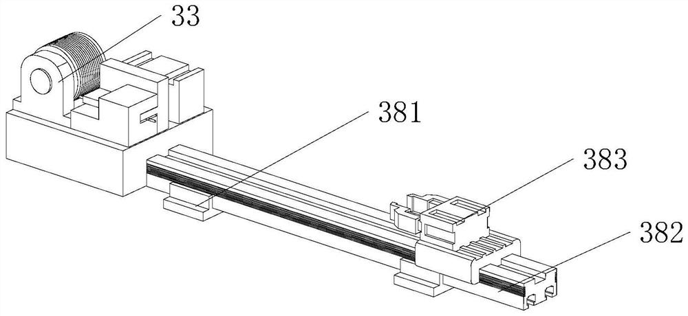
The invention relates to the technical field of mutual inductor machining, and discloses an automatic bending and wire-wrapping machine for mutual inductor copper skin. The automatic bending and wire-wrapping machine comprises a feeding assembly, a copper skin cutting assembly, a copper skin bending assembly, a discharging table, two wire pulling devices and two cutting and paying-off assemblies,wherein the copper skin cutting assembly is installed on the feeding assembly, and the copper skin bending assembly is installed at one end of the feeding assembly. The discharging table is installedat the end, away from the feeding assembly, of the copper skin bending assembly, the two cutting and paying-off assemblies are installed on the two sides of the copper skin bending assembly respectively, and the two cutting and paying-off assemblies are installed at the side ends of the two wire pulling devices respectively. Coiled copper skin can be automatically slit into copper skins of the needed size, meanwhile, the copper skins can be automatically fed, the two sides of each copper skin are automatically bent in the length direction, leads are automatically placed on the bent parts, thebent parts are flattened, and a series of operation of automatic discharging is conducted.

Description

technical field [0001] The invention relates to the technical field of transformer processing, in particular to an automatic bending and wrapping machine for copper skin of a transformer. Background technique [0002] Transformer, also known as instrument transformer, is a general term for current transformer and voltage transformer. It can change high voltage into low voltage and high current into small current for measurement or protection system. Its function is mainly to convert high voltage or high current into standard low voltage (100V) or standard small current (5A or 1A, both refer to rated value) in proportion, so as to realize the standardization and miniaturization of measuring instruments, protection equipment and automatic control equipment. change. At the same time, the transformer can also be used to isolate the high-voltage system to ensure the safety of people and equipment. The copper skin of the transformer has two functions: 1. Internally: uniform ele...

Claims


Application Information

Patent Timeline
Patent Type & Authority Applications(China)
IPC IPC(8): B21D5/00B21D43/02B23P23/04H01F41/00
CPCB21D5/00B21D43/02B23P23/04H01F41/00
Inventor 刘琼
Owner 刘琼
Learn More