
Large-flow, high-drop drainage drop well and its multi-layer energy dissipation construction method

A technology of large flow and falling wells, which is applied in drainage structures, waterway systems, water supply devices, etc., can solve problems such as land shortage, and achieve the effect of simple structure, ensuring safety, and clear process

Active Publication Date: 2018-02-06
CMCU ENG
View PDF6 Cites 2 Cited by
  • Summary
  • Abstract
  • Description
  • Claims
  • Application Information

AI Technical Summary

Problems solved by technology

[0007] In view of this, one of the objectives of the present invention is to provide a large-flow, high-drop drainage drop well to solve the energy dissipation problems of large flow and large drop that are not involved in traditional drainage drop wells; at the same time, the present invention The second purpose is to provide a multi-layer energy dissipation construction method with land-saving effect, and provide reference for the design of drop wells in built-up areas with tight land use and dense pipe network

Method used


Image

  • Large-flow, high-drop drainage drop well and its multi-layer energy dissipation construction method
  • Large-flow, high-drop drainage drop well and its multi-layer energy dissipation construction method

Examples


Embodiment Construction

[0041] The preferred embodiments of the present invention will be described in detail below in conjunction with the accompanying drawings; it should be understood that the preferred embodiments are only for illustrating the present invention, rather than limiting the protection scope of the present invention.

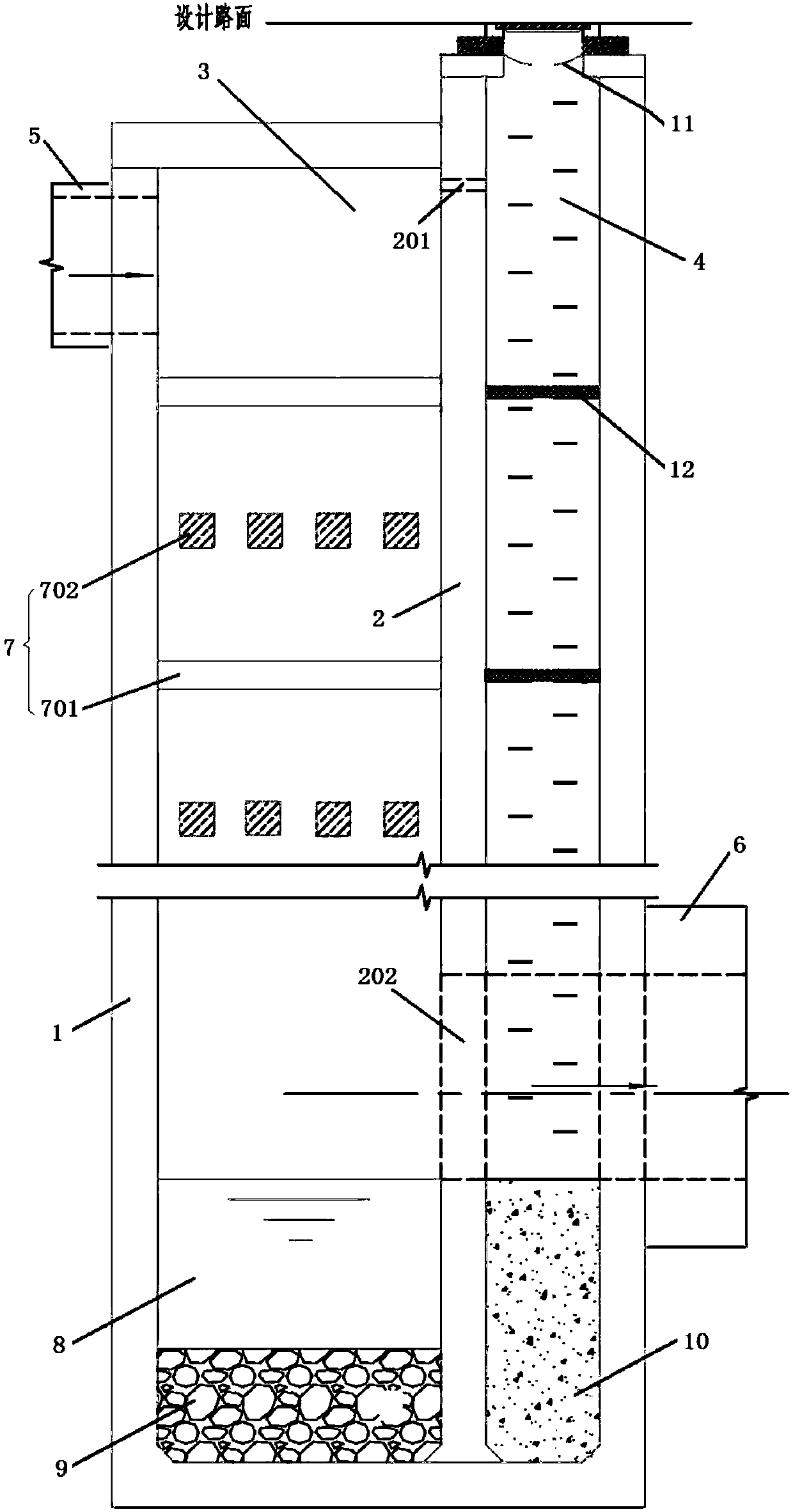
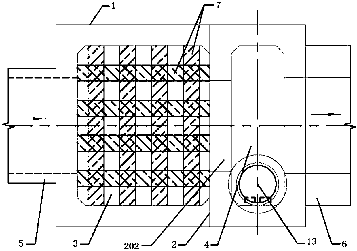
[0042] Such as Figure 1-2 As shown, a large-flow, high-drop drainage drop well in this embodiment is mainly composed of a well body 1, a partition wall 2, a drop chamber 3, an inspection room 4, an inlet pipe 5 and an outlet pipe 6, wherein the partition The wall 2 divides the well body 1 into two parts, the drop chamber 3 and the maintenance room 4. The drop chamber 3 includes a well chamber (unmarked) on the upper part and a hydraulic energy dissipation layer 8 on the lower part. The well chamber and the hydraulic energy dissipation The layer 8 is directly connected vertically, and the water inlet pipe 5 is used for the upstream drainage pipe culvert system to commun...


PUM


Abstract

The invention discloses a high-flow-rate great-dropping-difference water discharging drop well and a multilayer energy dissipation construction method thereof. The drop well consists of a well body, a partition wall, a drop chamber, an overhaul chamber, a water inlet pipe and a water outlet pipe, wherein the well body is separated into the drop chamber and the overhaul chamber by the partition wall; the drop chamber comprises a well chamber and a hydraulic energy dissipation layer; the water inlet pipe communicates with the upper part of the well chamber; a grill energy dissipation layer is arranged in the well chamber, and comprises a plurality of pile beam groups separated at equal intervals; the two adjacent pile and beam groups are in longitudinal and transverse staggered arrangement in the space; the water outlet pipe is arranged in the overhaul chamber and communicates with the lower part of the well chamber through a water passing hole formed in the lower part of the partition wall; in addition, the bottom surface of the inner cavity of the water outlet pipe and the top surface of the hydraulic energy dissipation layer are at the same elevation; the upper part of the partition wall is provided with an exhaust hole communicating the well chamber with the overhaul chamber. The drop well can solve the energy dissipation problems of high flow rate and great dropping difference which are not related in the conventional water discharging drop well; meanwhile, the multilayer energy dissipation construction method has the land saving effect, and provides the reference for the design of the drop well in the constraint resource and dense pipe network building regions.

Description

technical field [0001] The invention belongs to the technical field of municipal drainage engineering, and relates to structures for falling water of urban drainage pipes, in particular to a large-flow, high-drop drainage falling well and a multi-layer energy dissipation construction method thereof. Background technique [0002] Municipal drainage pipes mainly include sewage pipes, rainwater pipes and combined rainwater and sewage pipes. All three pipelines involve the arrangement of inspection wells. According to the "Outdoor Drainage Design Code (GB50014-2006<2014 Edition>)" (referred to as the Outdoor Drainage Design Code, the same below), "The location of the inspection well should be located at the intersection, turning, pipe diameter or slope change, Drops and at regular intervals on straight pipe sections.” [0003] The drop well is an important form of the inspection well. The drop well is used to solve the energy dissipation problem of gravity flow drainage ...

Claims


Application Information

Patent Timeline
Patent Type & Authority Patents(China)
IPC IPC(8): E03F5/02
CPCE03F5/02E03F5/021E03F2201/00
Inventor 李良富
Owner CMCU ENG
Learn More