
Mounting structure of soar-grille hyperbolic cantilever and mounting method of soar-grille hyperbolic cantilever

An installation method and a technology for installing structures, which are applied in building construction, building material processing, construction, etc., can solve the problems of high difficulty in stable control of super-long components, large slenderness ratio of components, and high height, so as to ensure installation quality and Progress, fewer auxiliary processes, steps and independent effects

Active Publication Date: 2016-11-09
CHINA CONSTR EIGHT ENG DIV CORP LTD
View PDF6 Cites 0 Cited by
  • Summary
  • Abstract
  • Description
  • Claims
  • Application Information

AI Technical Summary

Problems solved by technology

However, in the implementation process, although the cross-sectional size of this type of member is large, due to the excessive length, the slenderness ratio of the member itself is too large, and the cross-sectional characteristics are relatively soft; The structure, the center of gravity of a single member is protruding, and is not in the same plane. The entire length of the member is only tied or supported at both ends, and there is no inflection point support in the middle. It is quite difficult to control the stability of the super-long member during installation

Method used


Image

  • Mounting structure of soar-grille hyperbolic cantilever and mounting method of soar-grille hyperbolic cantilever
  • Mounting structure of soar-grille hyperbolic cantilever and mounting method of soar-grille hyperbolic cantilever
  • Mounting structure of soar-grille hyperbolic cantilever and mounting method of soar-grille hyperbolic cantilever

Examples


Embodiment Construction

[0033] In order to facilitate the understanding of the structure of the present invention, the following description will be made in conjunction with the accompanying drawings and embodiments.

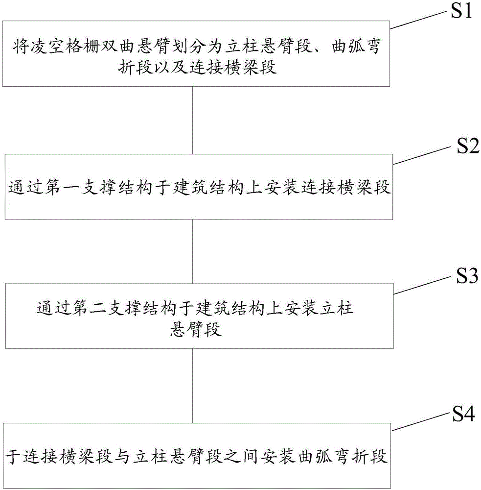
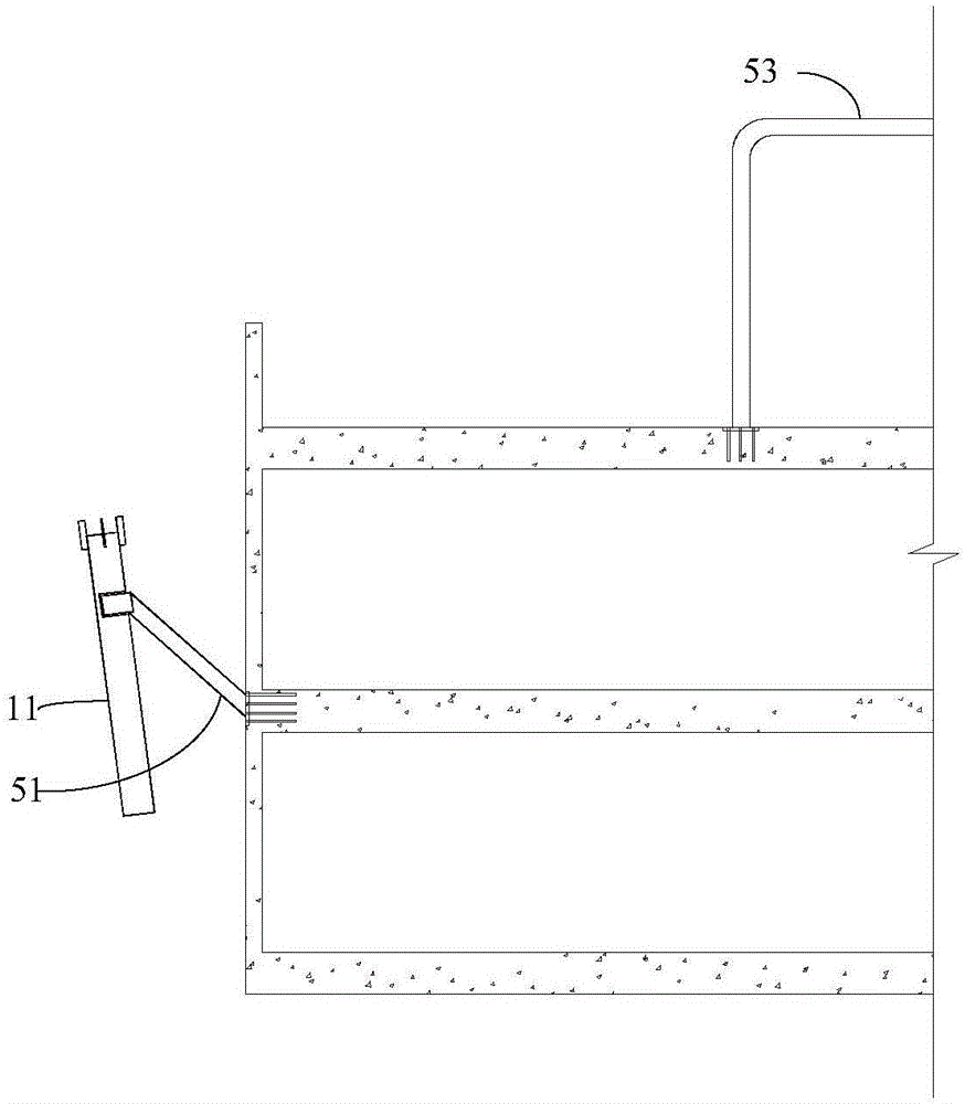
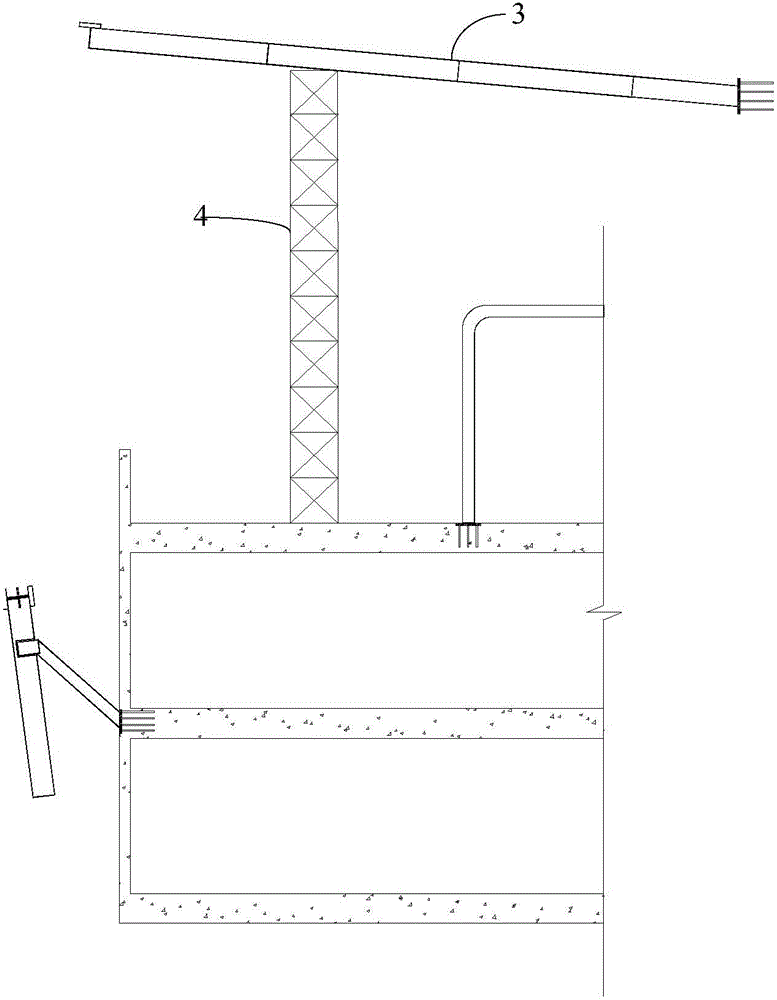
[0034] Please refer to figure 1 , Figure 2 to Figure 4 , figure 1 It shows a flow chart of the steps of the installation method of the volley grid hyperbolic cantilever of the present invention; Figure 2 to Figure 4 It shows the construction diagram of the installation method of the volley grid hyperbolic cantilever of the present invention.

[0035] The invention provides a method for installing a volley grid hyperbolic cantilever, comprising:

[0036] Step S1: Divide the volley grid hyperbolic cantilever into column cantilever section 1, curved arc bending section 2 and connecting beam section 3.

[0037] Specifically, when step S1 is executed, the volley grid hyperbolic cantilever is divided into the column cantilever section 1 arranged on the side of the building structure 6,...


PUM


Abstract

The invention discloses a mounting structure of a soar-grille hyperbolic cantilever and a mounting method of the soar-grille hyperbolic cantilever. The mounting method includes: dividing the soar-grille hyperbolic cantilever into a column cantilever section, a curve bending section and a connection beam section; mounting the connection beam section on an architectural structure through a first support structure; mounting the column cantilever section on the architectural structure through a second support structure; mounting the curve bending section on the space between the connection beam section and the column cantilever section. The soar-grille hyperbolic cantilever is divided into the column cantilever section, the curve bending section and the connection beam section for mounting, and the first support structure and the second support structure are arranged on the architectural structure for auxiliary mounting, so that the mounting method is simple and independent in step, on-site assembly with fewer auxiliary processes can be achieved, and mounting quality and progress of a project are guaranteed.

Description

technical field [0001] The invention relates to the field of building construction, in particular to an installation structure of a volley grid hyperbolic cantilever and an installation method thereof. Background technique [0002] With the rapid rise of the current industrialization of building steel structures, the external steel roofs of large-scale building structures have been applied and developed unprecedentedly, and super-long integrated steel beams and columns are emerging in endlessly, and are widely used in various tall and high-altitude space components. However, in the implementation process, although the cross-sectional size of this type of member is large, due to the excessive length, the slenderness ratio of the member itself is too large, and the cross-sectional characteristics are relatively soft; The structure, the center of gravity of a single member is protruded outward, and is not in the same plane. The entire length of the member is only tied or suppor...

Claims


Application Information

Patent Timeline
Patent Type & Authority Applications(China)
IPC IPC(8): E04B1/24E04G21/18
CPCE04B1/2403E04G21/1841
Inventor 李洪杰张强刘瑞雪刘文斗王志强
Owner CHINA CONSTR EIGHT ENG DIV CORP LTD
Learn More