Cast-in-place beam reinforcement cage binding installation multi-function trolley

A technology of steel cages and cast-in-place beams, which is used in construction, building structure, and building materials processing, etc., can solve the problems of difficult adjustment of steel bars, increased labor input, inconvenient movement, etc., and saves human resources and auxiliary materials. , Reduce labor intensity and ensure the effect of installation quality

Pending Publication Date: 2019-02-15
JIANGSU NANTONG NO 6 CONSTR GRP
View PDF8 Cites 12 Cited by
  • Summary
  • Abstract
  • Description
  • Claims
  • Application Information

AI Technical Summary

Problems solved by technology

[0004] 1. It takes time and effort to form the reinforcement cage with the help of temporarily erected steel pipe brackets. The installation and disassembly consumes a lot of labor, and a large amount of auxiliary materials are invested, which increases the project cost.
[0005] 2. After the beam stirrups are transported to the floor, they need to be transported twice on site, and the longitudinal bars are inserted one by one, which takes up the installation and construction period of the steel bars, and the work efficiency is low, and the labor input increases
[0006] 3. The specification requires that the distance between the longitudinal bars on the upper two floors of the beam ≥ max (25, d), and the straight section of the stirrup end is bent at 135° to withstand the second row of longitudinal bars. Generally, it is moved down and bound on site, resulting in the reinforcement The stress state in the structure changes, reducing the bearing capacity and seismic performance of the component
[0007] 4. It is necessary to lift the steel cage to replace the temporary support and sink the skeleton into the mold, which requires a lot of labor, and manual lifting and landing requires the cooperation of many people. The labor intensity of the workers is high, the construction speed is slow, and it is difficult to ensure the accurate installation position; chain hoists The structure of the bracket is complicated, it is inconvenient to move, and the investment in equipment increases; using a tower crane to lift and land will occupy a large amount of mechanical resources, and it is difficult to adjust the position of the steel bars, and it is even more difficult to ensure the installation accuracy
[0008] 5. The reinforcement at the joints of the beam and column is dense, and it is difficult to ensure that the overall reinforcement cage falls synchronously when the beam sinks into the mold. The longitudinal reinforcement of the beam is easy to get stuck in the column reinforcement, or the reinforcement cage is shifted during the falling process, causing the column reinforcement to be squeezed by the beam reinforcement. , or the beam reinforcement skeleton is arched and deformed, resulting in unqualified installation quality; and it is difficult to bind the column stirrups in the node area, and there are quality defects such as omission of stirrups or accumulation of stirrups
[0009] 6. If the reinforcement cage of the beam is deformed, the thickness of the protective layer on the side of the beam will inevitably fail to meet the design requirements. At the same time, the stirrup will loosen and slip, or even skew, making it difficult to restore the original shape, changing the position and stress state of the steel bar in the component, resulting in Hidden dangers of structural quality and safety
[0010] 7. At present, there is a lack of an updated process of binding the outside of the cast-in-place beam reinforcement cage mold into the mold, and the traditional method has been used. The operation level and sense of responsibility of the skilled workers are uneven, and there are bottlenecks in quality management. The traditional construction method of the cast-in-place beam reinforcement project Defects have been around for a long time

Method used


Image

  • Cast-in-place beam reinforcement cage binding installation multi-function trolley
  • Cast-in-place beam reinforcement cage binding installation multi-function trolley
  • Cast-in-place beam reinforcement cage binding installation multi-function trolley

Examples


Embodiment Construction

[0032] The following will clearly and completely describe the technical solutions in the embodiments of the present invention with reference to the accompanying drawings in the embodiments of the present invention. Obviously, the described embodiments are only some, not all, embodiments of the present invention. All other embodiments obtained by persons of ordinary skill in the art based on the embodiments of the present invention belong to the protection scope of the present invention.

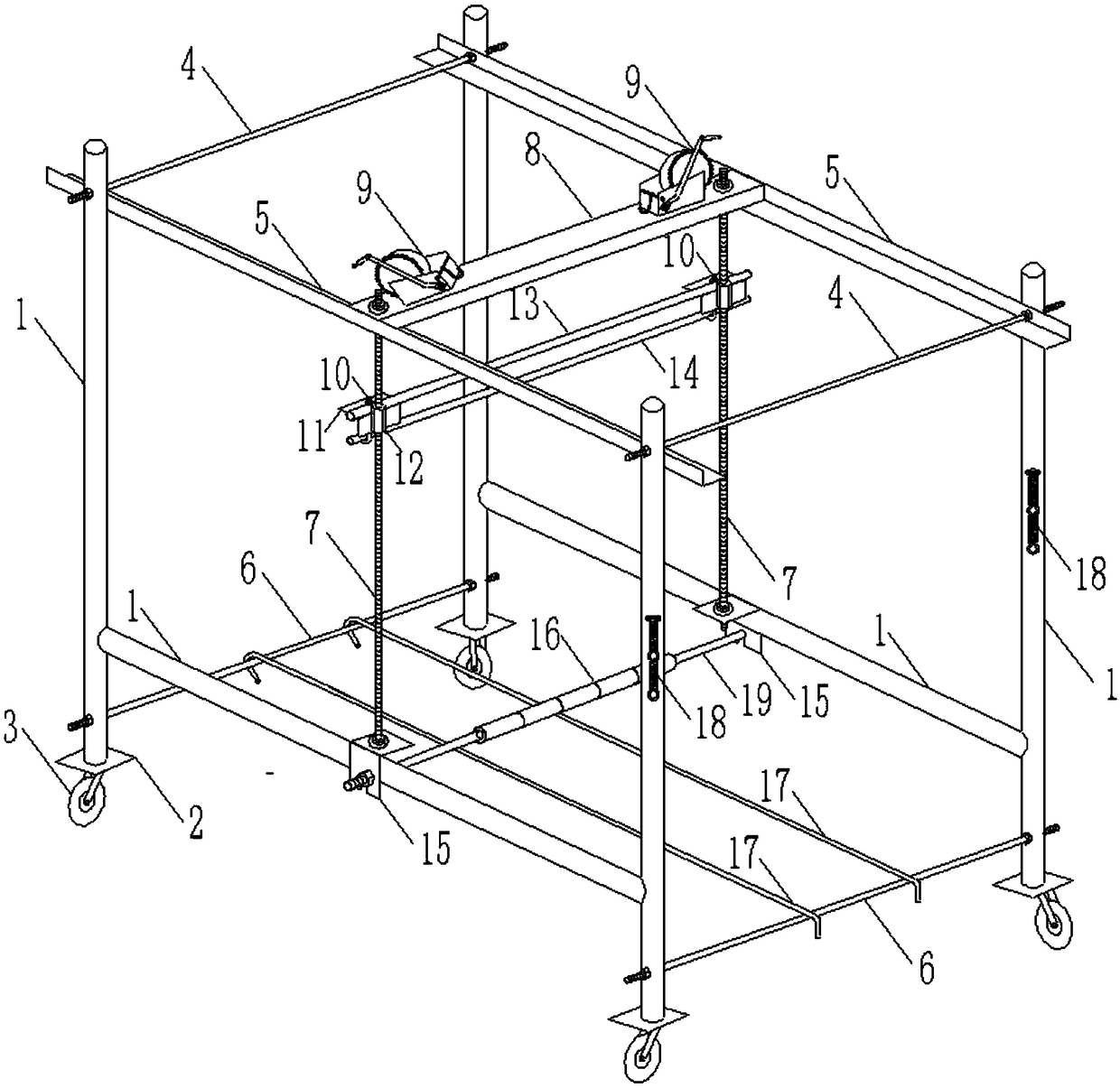
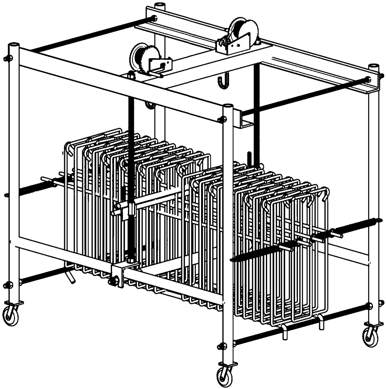
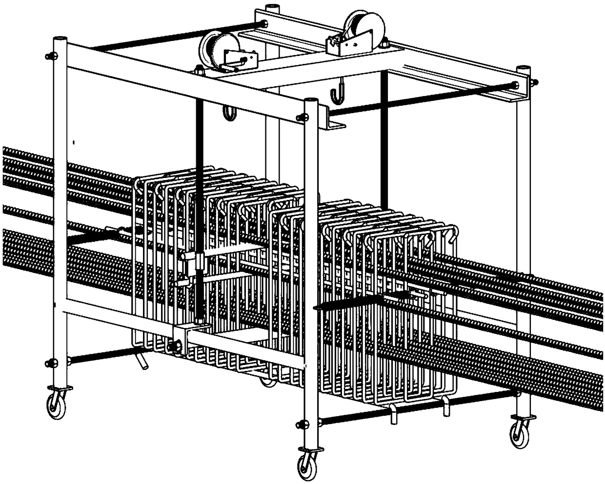
[0033] Such as Figure 1-4 As shown, according to the embodiment of the present invention, a cast-in-place beam reinforcement cage binding and installation multifunctional trolley includes a rectangular tubular vehicle body frame extending along the front and rear directions, and the openings at the front and rear ends of the vehicle body frame are connected with the reinforcement cage hoops. Corresponding to the ribs, the first cross brace 13, the second cross brace 14 and the third cross br...


PUM


Abstract

The invention discloses a cast-in-place beam reinforcement cage binding installation multi-function trolley. The cast-in-place beam reinforcement cage binding installation multi-function trolley comprises a rectangular tubular trolley body frame extending in the front-rear direction, and openings at the front and rear ends of the trolley body frame correspond to reinforcement cage stirrups. A first transverse support, a second transverse support and a third transverse support are detachably arranged in the trolley body frame from top to bottom. The first transverse support, the second transverse support and the third transverse support separately extend in the left and right direction, and the first transverse support and the second transverse support can slide up and down synchronously. The trolley body frame is further internally provided with limiting screws corresponding to the reinforcement cage stirrups in a penetrating mode, and the limiting screws extend in the front-rear direction. A plurality of tension springs are arranged at the front and the rear ends of the trolley body frame, and the limiting screws and the tension springs are detachably connected. The cast-in-placebeam reinforcement cage binding installation multi-function trolley has the characteristics and functions of loading and transporting, stirrup pre-penetrating, skeleton binding, vertical lifting and lowering, adjustable size, flexible movement and the like and replaces traditional cumbersome processes of temporary bracket building, on-site secondary transportation, multiple times of replacing andsupporting, manual or mechanical lifting of the reinforcement cage into a mold.

Description

technical field [0001] The invention relates to the technical field of tools for binding and installing cast-in-place beam reinforcement cages, in particular to a multifunctional trolley for binding and installing cast-in-place beam reinforcement cages. Background technique [0002] In the current conventional frame, frame-shear wall structure system, the production and installation of steel reinforcement works is very important in the structure construction. Especially the cast-in-place frame beam, as the most important stress-bearing member in the upper frame of the bearing building, forms a spatial structure system together with vertical members such as columns and walls. Durability and anti-crack and anti-seismic performance have important influences, involving the safety of concrete structures, and are key detection indicators in the quality acceptance of concealed projects. "Code for Construction Quality Acceptance of Concrete Structure Engineering" GB50204-2015 speci...

Claims


Application Information

Patent Timeline
Patent Type & Authority Applications(China)
IPC IPC(8): E04G21/12
CPCE04G21/123
Inventor 王祥争秦凤斌褚志军吴爱军王忠荣冯冲汪军李键高莹顾明萃解英朝陈锋华冯欣秦林华孙海龙王志勇
Owner JIANGSU NANTONG NO 6 CONSTR GRP
Why Eureka
Try Eureka