
Connecting device

A connecting device and rotational connection technology, applied in the direction of bridge parts, building components, bridges, etc., can solve the problems of difficult installation, high production cost, local stress concentration, etc., achieve simple structure, reduce installation difficulty, and solve local stress. concentrated effect

Inactive Publication Date: 2016-11-09
GUANGDONG KIN LONG HARDWARE PROD CO LTD
View PDF4 Cites 0 Cited by
  • Summary
  • Abstract
  • Description
  • Claims
  • Application Information

AI Technical Summary

Problems solved by technology

[0004] Based on this, it is necessary to provide a connecting device for the problems that the cable truss is prone to local stress concentration, difficult to install and high in production cost.

Method used


Image

  • Connecting device
  • Connecting device
  • Connecting device

Examples


Embodiment Construction

[0028] In order to facilitate the understanding of the present invention, the connecting device will be described in a more comprehensive manner with reference to the relevant drawings. The preferred embodiment of the connecting device is shown in the attached drawings. However, the connecting device can be implemented in many different forms and is not limited to the embodiments described herein. On the contrary, the purpose of providing these embodiments is to make the disclosure of the connection device more thorough and comprehensive.

[0029] Unless otherwise defined, all technical and scientific terms used herein have the same meaning as commonly understood by those skilled in the technical field of the present invention. The terminology used in the description of the connection device herein is only for the purpose of describing specific embodiments, and is not intended to limit the present invention. The term "and / or" as used herein includes any and all combinations of ...


PUM


Abstract

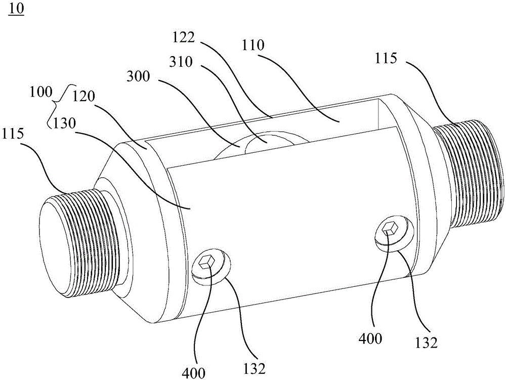
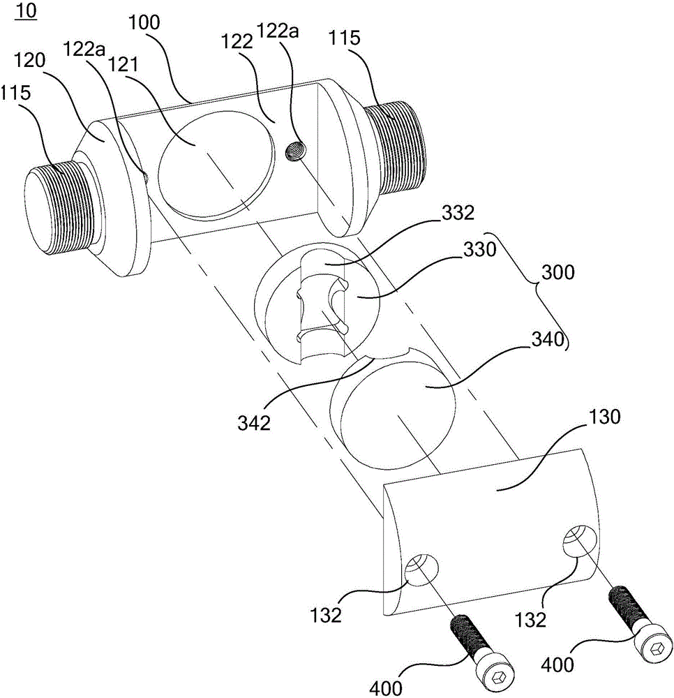
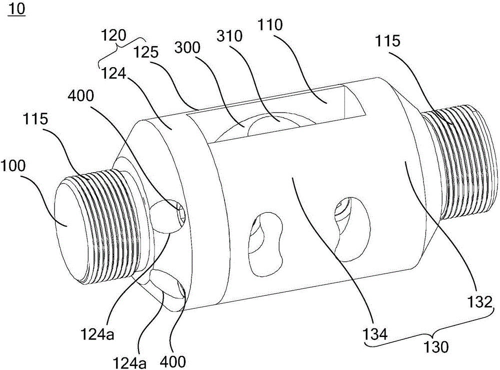
The invention relates to a connecting device which is used for connecting an inhaul cable and a supporting rod. The connecting device comprises a shell and a cable clamping assembly. The shell is provided with a cavity and used for being connected with the connecting rod. The cable clamping assembly is located in the cavity and rotatably connected to the inner wall of the cavity, and the cable clamping assembly is provided with cable holes for accommodating the inhaul cable. According to the connecting device, due to the fact that the cable clamping assembly is rotatably connected to the inner wall of the cavity, the cable clamping assembly can rotate according to the tension angle of the inhaul cable, so that the joint between the inhaul cable and the supporting rod is prevented from being bent, and the problem that a cable truss is prone to local stress concentration is solved accordingly; due to the fact that the connecting devices are used for connecting the inhaul cables and the supporting rods in different positions of the cable truss, the connecting devices located in different positions can be identical, and errors generated after assembling of the cable truss can be reduced; and the connecting device is simple in structure, the inhaul cable and the supporting rod can be conveniently connected and mounted, and thus the mounting difficulty of the cable truss can be greatly reduced.

Description

Technical field [0001] The present invention relates to the technical field of connection, in particular to a connection device. Background technique [0002] Cables are widely used in glass curtain walls due to their high tensile strength and compact structure characteristics. With the development of point supporting glass curtain wall technology, the area of ​​the curtain wall gradually increases. However, the greater the span of the cable on the curtain wall, the worse the rigidity of the cable. In order to increase the stiffness of the cables, trusses are added to the curtain wall, and the cables located around the curtain wall are connected by the trusses, so that a single cable net forms a cable truss. [0003] The general cable truss is stretched in a fish-belly or parabolic way. In order to ensure the shape and structure of the cable truss, the pressure block at the connection between the support rod and the cable needs to be designed according to the tension angle of th...

Claims


Application Information

Patent Timeline
Patent Type & Authority Applications(China)
IPC IPC(8): E04B2/88E04B1/38E01D19/00
CPCE04B2/88E01D19/00E04B1/38
Inventor 白宝鲲
Owner GUANGDONG KIN LONG HARDWARE PROD CO LTD
Learn More