A switch frequency conversion component

A switch and component technology, applied in the field of testing, can solve the problems of uncertainty in measurement results, complex testing, and difficulty in identifying false signals, and achieve the effects of reducing the number of interconnection operations, improving testing efficiency, and reducing processing difficulty.

Active Publication Date: 2018-10-30
THE 41ST INST OF CHINA ELECTRONICS TECH GRP
View PDF8 Cites 2 Cited by
  • Summary
  • Abstract
  • Description
  • Claims
  • Application Information

AI Technical Summary

Problems solved by technology

[0009] It can be known from the principle of the measurement signal frequency of the millimeter-wave module in formula (1), since there is no pre-selection filter, it will be very difficult to determine the "±" in the formula to accurately measure the frequency of the signal under test
[0010] Since the input terminal of the millimeter-wave spread spectrum module is a standard rectangular waveguide, and the waveguide has a low-frequency cut-off characteristic, the working frequency of the millimeter-wave spread spectrum module can only realize the spectrum test whose frequency range covers one waveguide frequency band, and cannot achieve complete frequency coverage from low frequency to waveguide frequency band. , and the millimeter wave spread spectrum module has the problems of low compression point and difficult identification of false signals
In order to realize frequency scanning from low frequency to waveguide frequency band, multiple connection tests can only be carried out with millimeter wave spread spectrum module and without millimeter wave spread spectrum module, and the test efficiency is low
And because of the need to transfer between the waveguide and the coaxial port, the test is more complicated, and the uncertainty of the measurement result is introduced

Method used


Image

  • A switch frequency conversion component
  • A switch frequency conversion component

Examples


Embodiment Construction

[0033] The following will clearly and completely describe the technical solutions in the embodiments of the present invention with reference to the accompanying drawings in the embodiments of the present invention. Obviously, the described embodiments are only some, not all, embodiments of the present invention. Based on the embodiments of the present invention, all other embodiments obtained by persons of ordinary skill in the art without making creative efforts belong to the protection scope of the present invention.

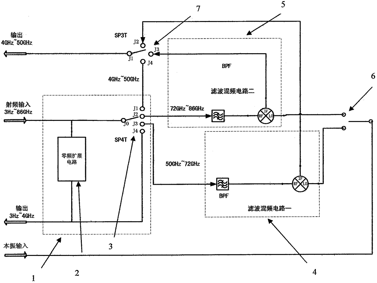
[0034] The 3Hz-86GHz switch frequency conversion component realized by the present invention includes a radio frequency input duplex circuit composed of a zero-frequency extension circuit and a single-pole multi-throw switch to realize separate transmission of low-frequency input signals and high-frequency input signals. The zero-frequency extension circuit has low-loss transmission characteristics in the low-frequency range, and has a good filtering effect on ...


PUM


Abstract

The invention provides a switching frequency conversion component, which includes a radio frequency input duplex circuit, and the radio frequency input duplex circuit is composed of a zero-frequency expansion circuit and a single-pole four-throw switch, so as to realize the separation and transmission of a low-frequency input signal and a high-frequency input signal; The frequency expansion circuit has the characteristics of low-loss transmission in the low-frequency range, and has a filtering effect on the high-frequency signal, so as to realize the low-loss transmission of the low-frequency input signal and the high-frequency input signal respectively; the two output ports output the low-frequency output signal respectively. and IF output signal. The switching frequency conversion component proposed by the invention can realize accurate measurement of signal frequency and power parameters of 3 Hz to 86 GHz in a single connection; and has the advantages of simple structure, low processing difficulty and low cost, and solves the problem of low test efficiency and low cost of the existing spectrum test scheme. The problem of poor measurement accuracy of frequency power parameters.

Description

technical field [0001] The invention relates to the technical field of testing, in particular to a switch frequency conversion component. Background technique [0002] With the development of millimeter-wave radar, guidance, communication and other systems, there is an urgent demand for high-performance broadband millimeter-wave spectrum analyzers with operating frequencies covering millimeter frequency bands, which are mainly used for the R&D and production of various microwave and millimeter-wave communication equipment and components testing and evaluation during the process. It is required that a spectrum analyzer can cover a wide enough frequency range to minimize the number of test instruments while meeting the test requirements of various communication equipment, reduce test cost, shorten test time and facilitate maintenance. [0003] At present, due to the limitation of technical conditions, it is impossible to realize the broadband pre-selection filter for frequenc...

Claims


Application Information

Patent Timeline
Patent Type & Authority Patents(China)
IPC IPC(8): G01R23/02
CPCG01R23/02
Inventor 代秀李立功姜万顺张枢郭小文朱伟峰韦柳泰徐从玉
Owner THE 41ST INST OF CHINA ELECTRONICS TECH GRP
Why Eureka
Try Eureka