Female connectors, male connectors and high-voltage and high-current electrical connectors

A high-current connector and plug-in technology, which is used in vehicle connectors, devices for connecting/disconnecting connecting components, and connections, can solve problems such as troublesome disassembly, prolonging the man-hours required for maintenance, and increasing the time for unplugging connectors.

Active Publication Date: 2019-03-01
唐兴然
View PDF11 Cites 0 Cited by
  • Summary
  • Abstract
  • Description
  • Claims
  • Application Information

AI Technical Summary

Problems solved by technology

In order to ensure the reliability of the connection, people often adopt more complicated means to realize the connection between the male connector and the female connector of the electrical connector, but this connection method is more troublesome to disassemble and will increase the time to remove the connector. , prolonging the man-hours required for maintenance

Method used


Image

  • Female connectors, male connectors and high-voltage and high-current electrical connectors
  • Female connectors, male connectors and high-voltage and high-current electrical connectors
  • Female connectors, male connectors and high-voltage and high-current electrical connectors

Examples


Embodiment 1

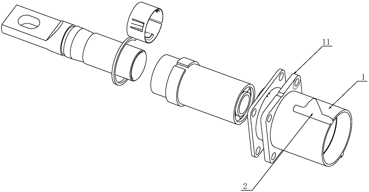
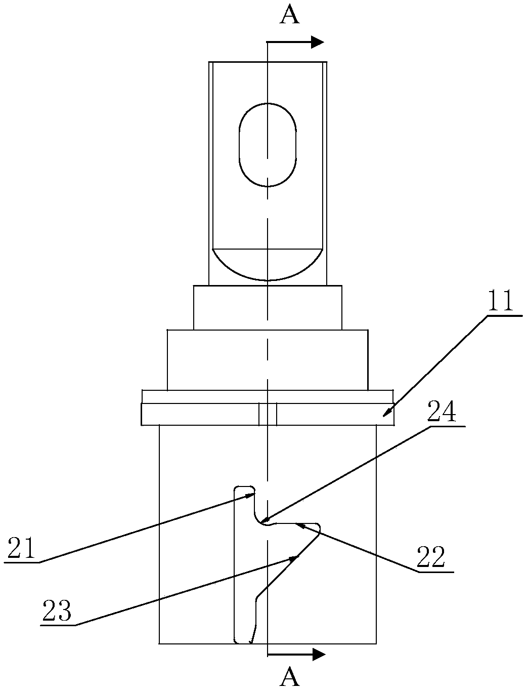
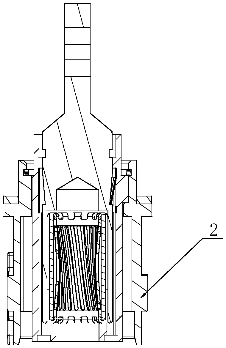
[0040] figure 1 It is a three-dimensional disassembly view of Embodiment 1 of the present invention, figure 2 It is a side view of Embodiment 1 of the present invention, image 3 yes figure 2 A-A sectional view of, Figure 4 It is a schematic structural view of the front-end assembly of the plug matched with the socket of Embodiment 1, Figure 5 yes Figure 4 bottom view. In the figure, the meanings of each reference mark are as follows: 1. Sleeve part; 11. Flange part; 2. Limiting boss; 21. A guide side wall; 22. B guide side wall; 23. C guide side wall; 24, limit pit; 3, positioning groove; 4, positioning convex rib.

[0041] A socket, comprising a sleeve part 1, the sleeve part 1 has an inner end and an outer end, the inner end of the sleeve part 1 is connected to a flange part 11 for installing the socket, and the outer circumference of the sleeve part 1 is provided with limited The positioning boss 2, the limiting boss 2 has a guiding side wall 21 and a second gu...

Embodiment 2

[0048] Image 6 It is a three-dimensional disassembled view of the front-end assembly of the plug according to Embodiment 2 of the present invention; Figure 7 It is a left view of the front end assembly of the plug according to Embodiment 2 of the present invention. In the figure, the same reference numerals as those used in the above-mentioned embodiments still use the definition of the reference numerals in the above-mentioned embodiments, and the meanings of the newly appearing reference numerals in the figure are as follows: 5. The first sleeve; 51, the first snap ring groove; 6, the second sleeve; 61, positioning column; 62, counterbore; 63, knurling; 7, the third sleeve; 71, the second snap ring groove; 8, torsion spring.

[0049] A plug mated with the above-mentioned socket includes a first sleeve 5 and a second sleeve 6, the second sleeve 6 is arranged on the outside of the first sleeve 5, and between the second sleeve 6 and the first sleeve 5 are connected in a rot...

Embodiment 3

[0053] Figure 8 It is a sectional view of Embodiment 3 of the present invention; Figure 9 It is a schematic diagram of the external structure in Embodiment 3 of the present invention; Figure 10 is a schematic diagram at different positions in the process of inserting the plug into the socket; Figure 11 It is a schematic diagram of the movement trajectory of the positioning post 1 relative to the limiting boss during the plug insertion into the socket. It should be noted that, because the counterbore 62 is opened on the opposite side of the positioning post 61, the position change of the positioning post 61 can be represented by the position change of the counterbore 62. The same reference numerals in the drawings still use the definitions of the reference numerals in the above-mentioned embodiments.

[0054] A high-voltage and high-current connector, comprising any one of the above-mentioned sockets and any one of the above-mentioned plugs.

[0055] Specifically, durin...


PUM


Abstract

The invention relates to a female plug, a male plug, and a high-voltage large-current connector equipped with the female plug and the male plug. The female plug comprises a sleeve part which has an inner end and an outer end. A limiting boss is arranged on the outer circumference of the sleeve part. The limiting boss is provided with a guide sidewall A and a guide sidewall B. the guide sidewall B is arranged perpendicular to the axial direction of the sleeve part. The inner end of the guide sidewall B and the guide sidewall A are in the circumferential direction of the sleeve part. The female plug is further provided with a second circumferential positioning part which matches with a first circumferential positioning part on the male plug to form a circumferential positioning structure, and the second circumferential positioning part and the limiting boss are circumferentially fixed. Through matching of the male plug and the female plug, convenient disassembly is achieved without reducing the reliability of connection.

Description

technical field [0001] The invention belongs to the technical field of electrical connectors, and in particular relates to a female connector, a male connector and a high-voltage and high-current electrical connector provided with the male connector and the female connector. Background technique [0002] High-voltage and high-current electrical connectors are important components of the electrical system of new energy vehicles. They are mainly used to realize electrical connections in places where large currents pass, such as inverters, motors, and batteries. In order to ensure the reliability of the connection, people often adopt more complicated means to realize the connection between the male connector and the female connector of the electrical connector, but this connection method is more troublesome to disassemble and will increase the time to pull out the connector. , prolonging the man-hours required for maintenance. Contents of the invention [0003] In order to o...

Claims


Application Information

Patent Timeline
Patent Type & Authority Patents(China)
IPC IPC(8): H01R13/629H01R13/622H01R13/639
CPCH01R13/622H01R13/629H01R13/639H01R2201/26
Inventor 唐兴然
Owner 唐兴然
Why Eureka
Try Eureka