Imaging mechanism and terminal

An imaging and housing technology, applied in the field of image shooting, can solve the problems of inconsistent image clarity, camera aberration, focusing failure, etc., to avoid focusing failure, reduce the aberration, and achieve consistent image clarity.

Inactive Publication Date: 2016-11-09
SHENZHEN GIONEE COMM EQUIP
View PDF5 Cites 3 Cited by
  • Summary
  • Abstract
  • Description
  • Claims
  • Application Information

AI Technical Summary

Problems solved by technology

[0002] With the popularization of shooting equipment such as cameras and smart phones, taking pictures has become a common interest in people's daily life; but in the existing shooting equipment, there will be a glass cover in front of the camera. Only one side of the plate is curved, so the thickness between the two sides of the glass cover is different from place to place, so the refraction of light passing through the glass cover is naturally different, and this phenomenon will cause the camera to produce The difference will not only make the sharpness of the captured image inconsistent, but may even lead to focus failure

Method used


Image

  • Imaging mechanism and terminal
  • Imaging mechanism and terminal
  • Imaging mechanism and terminal

Examples


Embodiment approach 1

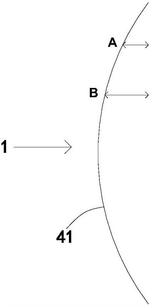
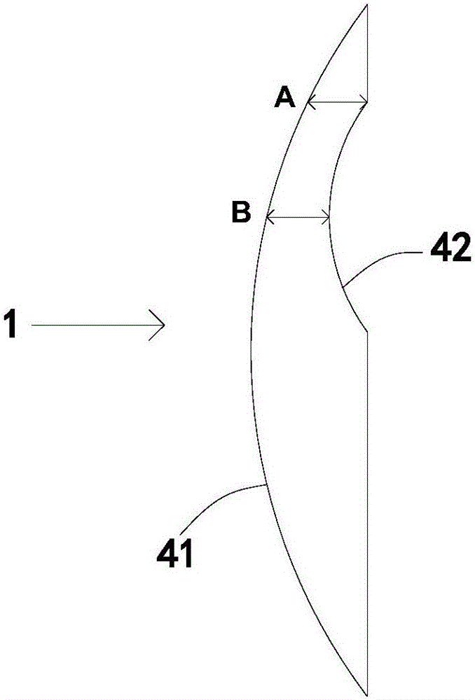
[0040] An imaging mechanism, comprising a glass cover 1 and a camera 2, one side of the glass cover 1 protrudes outward to form a first arc 41, the other side of the glass cover 1 is opposite to the camera 2, The glass cover 1 is provided with a second arc surface 42 at the position opposite to the camera 2, and the second arc surface 42 is formed by inward depression at the position opposite to the camera 2 of the glass cover 1, and the The distance between the first arc surface 41 and the second arc surface 42 is the same, the camera 2 is aimed at the area where the distance between the first arc surface 41 and the second arc surface 42 is the same, and the second arc surface 41 The coverage of the curved surface 42 is larger than the shooting range of the camera 2 .

Embodiment approach 2

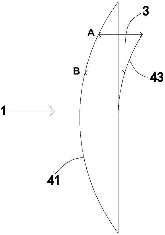
[0042] An imaging mechanism, comprising a glass cover 1 and a camera 2, one side of the glass cover 1 protrudes outward to form a first arc 41, the other side of the glass cover 1 is opposite to the camera 2, The glass cover plate 1 is provided with a glass sheet 3 opposite to the camera 2, a transparent glue layer is arranged between the glass cover plate 1 and the glass sheet 3, and the glass sheet 3 passes through the transparent glue layer. layer is adhered on the glass cover 1, wherein the glass cover 1 and the glass sheet 3 have the same refractive index; in addition, the glass sheet 3 is recessed inwardly opposite to the camera 2 to form a second Three arc surfaces 43, the distance between the first arc surface 41 and the third arc surface 43 is the same, and the camera 2 is aligned with the same distance between the first arc surface 41 and the third arc surface 43 area, and the coverage of the third arc surface 43 is larger than the shooting range of the camera 2 .

...


PUM


Abstract

The embodiment of the invention discloses an imaging mechanism and a terminal, belonging to the technical field of photographic equipment, wherein the imaging mechanism and the terminal both comprise a glass cover plate and a camera, one side face of the glass cover plate protrudes outwards to form a first cambered surface, the other side face of the glass cover plate is opposite to the camera, the glass cover plate is provided with a thickness difference elimination structure at a part opposite to the camera, and the thickness difference elimination structure is used for reducing thickness difference between the two side faces of the glass cover plate; in conclusion, in the imaging mechanism and the terminal provided by the invention, thickness difference between the two side faces of the glass cover plate is reduced through the thickness difference elimination structure, consequently, thickness of the glass cover plate tends to be uniform, and therefore, refraction generated by light passing through the glass cover plate naturally also tends to be same, namely, phase error generated by the camera is reduced, definition of photographed images is guaranteed to be consistent, and a situation of focusing failure is also avoided.

Description

technical field [0001] The present invention relates to the technical field of image capturing, in particular to an imaging mechanism and a terminal. Background technique [0002] With the popularization of shooting equipment such as cameras and smart phones, taking pictures has become a common interest in people's daily life; but in the existing shooting equipment, there will be a glass cover in front of the camera. Only one side of the plate is curved, so the thickness between the two sides of the glass cover is different from place to place, so the refraction of light passing through the glass cover is naturally different, and this phenomenon will cause the camera to produce The difference will not only make the sharpness of the captured image inconsistent, but may even lead to focus failure. Contents of the invention [0003] Embodiments of the present invention provide an imaging mechanism and a terminal, so that the thickness of the glass cover tends to be consisten...

Claims


Application Information

Patent Timeline
IPC IPC(8): H04M1/02H04N5/225
CPCH04M1/0264H04N23/50H04N23/57
Inventor 黄晓峰
Owner SHENZHEN GIONEE COMM EQUIP
Why Eureka
Try Eureka