
Shielding cylinder structure, shielding cover thereof and current transformer using shielding cylinder structure

A technology of current transformers and shielding tubes, which is applied in the direction of inductors, magnetic field/electric field shielding, prevention/reduction of unnecessary electric/magnetic effects, etc., can solve problems such as low efficiency, and achieve high processing efficiency.

Inactive Publication Date: 2016-11-09
平高集团威海高压电器有限公司 +2
View PDF9 Cites 4 Cited by
  • Summary
  • Abstract
  • Description
  • Claims
  • Application Information

AI Technical Summary

Problems solved by technology

[0005] The purpose of the present invention is to provide a shielding cover for the shielding cylinder structure, to solve the technical problem in the prior art that the efficiency of arc processing of the tip at the front end of the shielding cover is low; at the same time, the present invention also provides a Shielding cylinder structure using the above shielding case and current transformer using the shielding cylinder structure

Method used


Image

  • Shielding cylinder structure, shielding cover thereof and current transformer using shielding cylinder structure
  • Shielding cylinder structure, shielding cover thereof and current transformer using shielding cylinder structure
  • Shielding cylinder structure, shielding cover thereof and current transformer using shielding cylinder structure

Examples


Embodiment Construction

[0026] Embodiments of the present invention will be further described below in conjunction with the accompanying drawings.

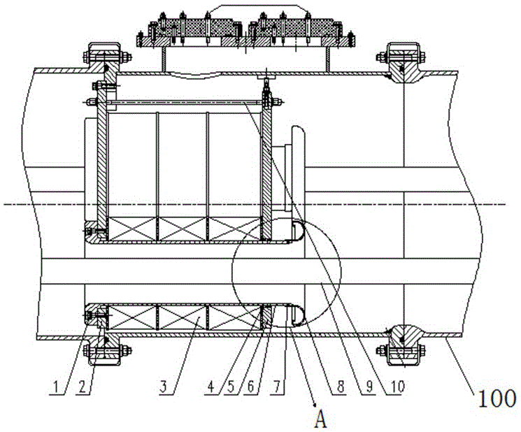
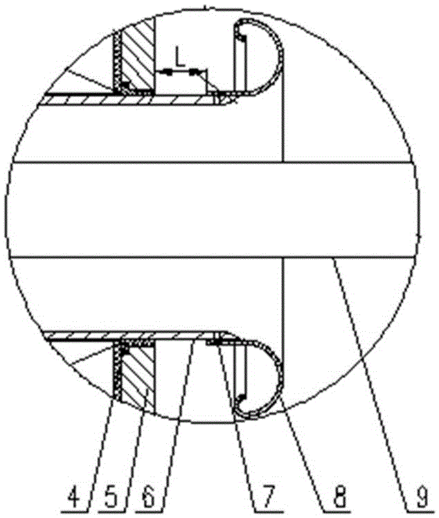
[0027] The specific embodiment of current transformer provided by the present invention, such as Figure 1 to Figure 7 As shown, the current transformer in this embodiment includes a shell, and a transformer body is arranged in the shell. The transformer body includes a front fixing plate 2 and a rear fixing plate 5 arranged at intervals along the front and rear directions, and the two fixing plates are circular plate structures. , A spacing adjustment screw 10 is provided between the front and rear fixing plates.

[0028] Three mounting holes uniformly distributed along the circumferential direction are respectively provided on each fixing plate, and a shielding cylinder structure is supported and assembled in each mounting hole, so that three shielding cover structures are uniformly distributed along the circumferential direction. Each shielding cylin...


PUM


Abstract

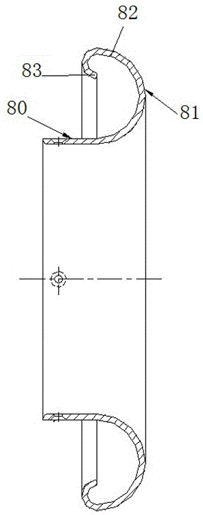
The invention relates to a shielding cylinder structure, a shielding cover thereof and a current transformer using the shielding cylinder structure. The shielding cylinder structure comprises a cylinder body. The shielding cover is arranged on the front end of the cylinder body. The shilding cover comprises a cover body. An everted edge folded outwards is arranged on the front end of the cover body. The everted edge a first folded segment, a second folded segment and a third folded segment which are in transition connection by circular arcs. The first folded segment extends frontwards and is folded outwards. The second folded segment extends backwards. The third folded segment is folded inwards to the inner side of the second folded segment. By means of folding, a tip end on the everted edge on the front end of the cover body can be effectively eliminated, and the influences caused by tip discharging are avoided. Compared with a mode that circular arc machining is carried out on the end part of the everted edge, the machining mode that the tip end is eliminated by means of folding is simpler, and the machining efficiency is relatively high.

Description

technical field [0001] The invention relates to a shielding cylinder structure, its shielding cover and a current transformer using the shielding cylinder structure. Background technique [0002] The current transformer for GIS is one of the important components of the gas-insulated metal-enclosed switch (GIS). Its main function is to measure the current, and it plays the role of measurement, measurement and protection. In GIS equipment, built-in and feed-through current transformers are mostly used. Since the transformer coil is directly installed inside the shell, and it is the secondary low-voltage end, it is easy to form an extremely uneven electric field with the primary high-voltage end, causing breakdown discharge and burning the transformer coil. Therefore, necessary protective measures must be taken for the transformer coil, that is, the shielding cylinder structure. [0003] In the authorized announcement number CN203118757U, a Chinese utility model patent disclo...

Claims


Application Information

Patent Timeline
Patent Type & Authority Applications(China)
IPC IPC(8): H05K9/00H01F27/36H01F38/30
CPCH01F27/36H01F38/30H05K9/00
Inventor 周茂欣刘威卢素梅张晓辉黄腾
Owner 平高集团威海高压电器有限公司
Learn More