
Multi-station bidirectional shearing device

A multi-station, shearing device technology, applied to household components, household utensils, and other household utensils, etc., can solve problems such as spending enough time cooling, product deformation, and occupation of manipulator positions, and achieve the effect of increasing the storage of tableware

Pending Publication Date: 2019-12-10
PINGYANG HAIHANG MACHINERY
View PDF1 Cites 0 Cited by
  • Summary
  • Abstract
  • Description
  • Claims
  • Application Information

AI Technical Summary

Problems solved by technology

[0004] However, in actual production and use, the applicant found that since the blade moves in one direction during shearing, the resistance force generated during shearing will be supported by the extrusion of the injection molded product and the positioning part. When the injection molded part comes out, its The temperature is high, and its own strength is low when it is not cooled, so it is easy to cause product deformation when the blade performs one-way cutting motion. If it takes enough time to cool the injection molded parts, it will occupy the manipulator position and delay the production efficiency. Therefore, it is necessary To further optimize and improve the existing problems, improve the cutting efficiency and smoothness, so as to reduce the deformation of the product, and at the same time ensure that the tableware can be stored in large capacity and cooled quickly after cutting

Method used


Image

  • Multi-station bidirectional shearing device
  • Multi-station bidirectional shearing device
  • Multi-station bidirectional shearing device

Examples


Embodiment Construction

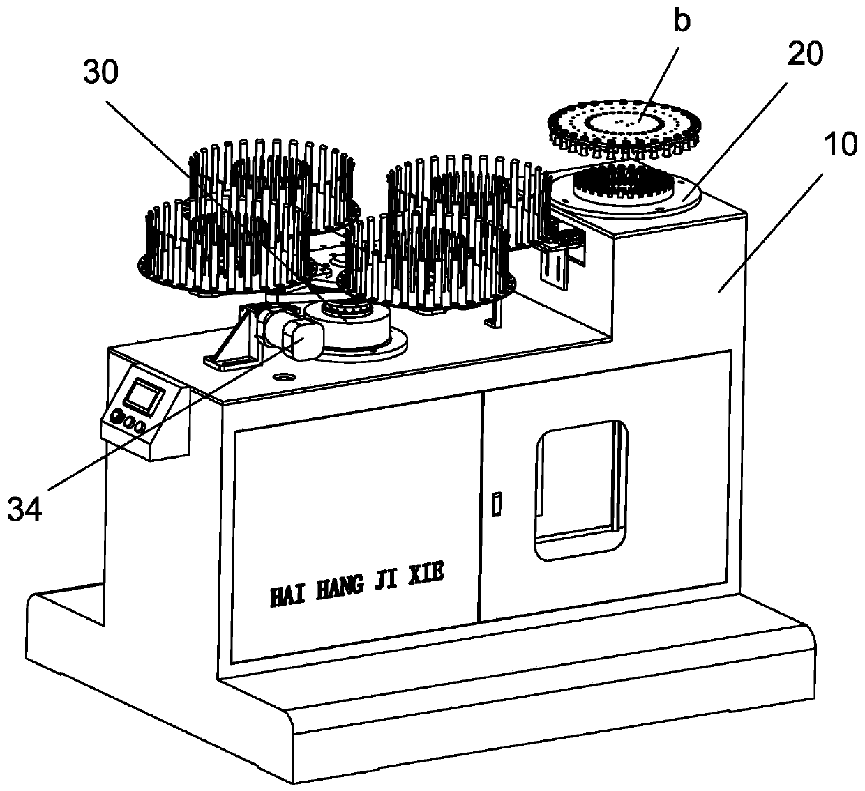
[0042] The specific implementation manners of the present invention will be further described in detail below in conjunction with the accompanying drawings and embodiments. The following examples are used to illustrate the present invention, but are not intended to limit the scope of the present invention.

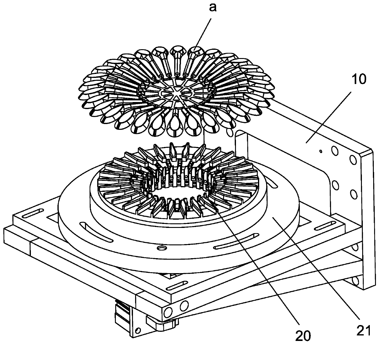
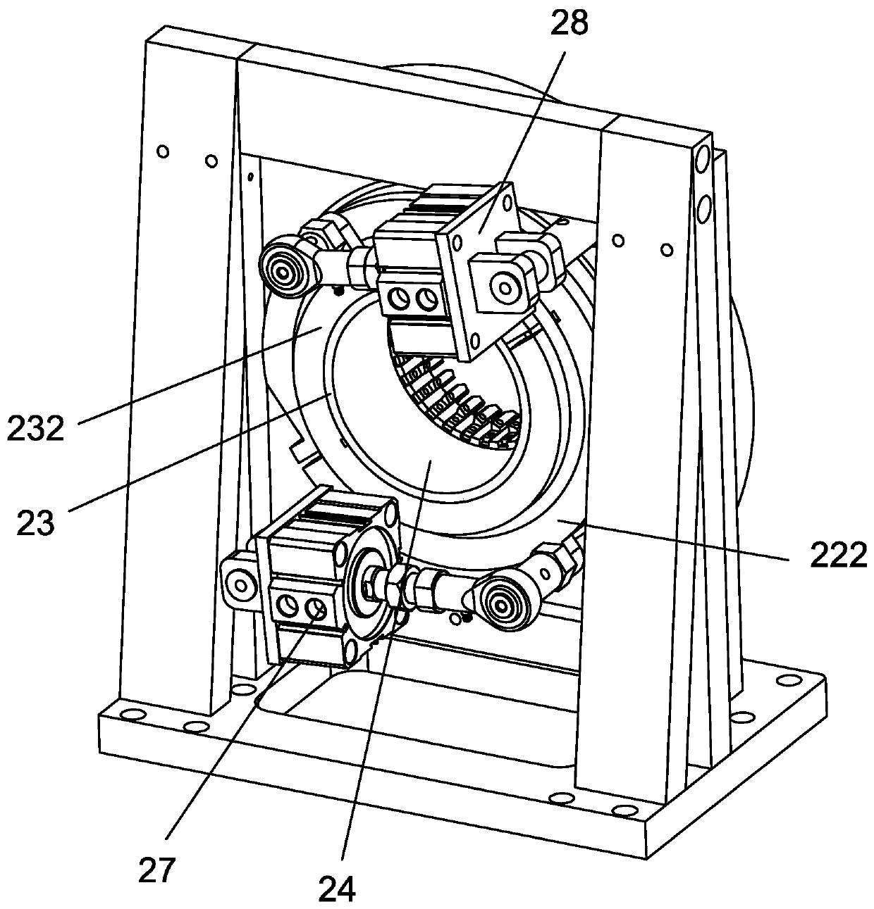
[0043] refer to Figure 1 to Figure 10 ,like Figure 1 to Figure 10 A kind of multi-station two-way shearing device shown, comprises frame 10, and described frame 10 is provided with shearing device 20 and station switching device 30, and described shearing device 20 comprises and is fixed on frame 10 The annular base 21, the upper surface of the annular base 21 is provided with a number of positioning parts 211 uniformly distributed along its circumference; the lower part of the annular base 21 is sequentially provided with outer knives that can rotate relative to the central axis of the annular base 21 Disc 22 and inner cutter disc 23, the outer cutter disc 22 and inne...


PUM


Abstract

The invention provides a multi-station bidirectional shearing device. The device comprises a machine frame, wherein a shearing device and a station conversion device are arranged on the machine frame,the shearing device comprises an annular base, and a positioning portion is arranged on the upper surface of the annular base; and an outer cutter disc and an inner cutter disc are arranged below theannular base, the side, facing the annular base, of the outer cutter disc is provided with sliding grooves which are formed in the radial direction of the outer cutter disc, outer blades are arrangedon the sliding grooves, the inner wall of a discharging hole of the inner cutter disc is provided with blade grooves in the circumferential direction of the discharging hole, the blade grooves are provided with inner blades, the top ends of the outer blades and the top ends of the inner blades are higher than the surface of the annular base, the blade edges of the outer blades face the rotating direction of the outer cutter disc, and the blade edges of the inner blades face the rotating direction of the inner cutter disc. According to the device, the smoothness after shearing of the runner ofan injection molding product can be improved, the deformation and burrs can be effectively reduced, cut tableware can be accurately received, the positioning is accurate, the storage capacity is large, and the cooling effect is good.

Description

technical field [0001] The invention relates to the field of trimming equipment for injection molding products, in particular to a multi-station bidirectional trimming device. Background technique [0002] The rapid development of today's food delivery industry makes the corresponding tableware in short supply. Therefore, in the eyes of many manufacturers, how to improve production efficiency and reduce the labor intensity of employees is a problem that needs to be solved. Tableware such as spoons and forks are generally produced by injection molding. When it is injected, it is often a mold with multiple cavities. The tableware is arranged in a circle, and the injection flow channel is set in the circle. Finally, after the injection molding is completed, the tableware is sucked by the suction cup of the manipulator at the same time and all are transferred to the cutting machine. Unified cutting on the equipment. Although there are batch cutting equipment on the market at pre...

Claims


Application Information

Patent Timeline
Patent Type & Authority Applications(China)
IPC IPC(8): B29C45/38B29C45/17B29L31/28
CPCB29C45/382B29C45/1769B29C45/0025B29C2045/0036B29L2031/286
Inventor 朱云锋叶维沣陈成丰朱育琛彭世才
Owner PINGYANG HAIHANG MACHINERY
Learn More