
Motorized spindle hydraulic radial locking mechanism

A technology of locking mechanism and motorized spindle, which is applied in metal processing machinery parts, metal processing equipment, feeding devices, etc., can solve the problems of complex assembly and axial movement of motorized spindle locking.

Inactive Publication Date: 2016-11-16
BEIJING CTB SERVO CO LTD
View PDF10 Cites 0 Cited by
  • Summary
  • Abstract
  • Description
  • Claims
  • Application Information

AI Technical Summary

Problems solved by technology

[0004] In order to solve the above-mentioned problems in the prior art, that is, in order to solve the problems of complex processing and assembly of the existing electric spindle locking device and the axial movement when the electric spindle is locked, the present invention provides a hydraulic radial lock for the electric spindle tightening mechanism, the electric spindle includes a rotating shaft and a spindle housing; it is characterized in that the hydraulic radial locking mechanism of the electric spindle includes a hydraulic seat fixed on the main shaft housing and a friction seat arranged on the hydraulic seat ring; the friction ring includes a radial installation part and an axial friction part, the radial installation part is fixedly connected to one end of the hydraulic seat, and the axial friction part is arranged radially inside the hydraulic seat; The hydraulic seat is provided with a hydraulic channel; during operation, hydraulic oil is injected into the hydraulic channel, and the hydraulic oil drives the friction ring to radially compress the rotating shaft, and then brakes and locks the shaft. Shaft

Method used


Image

  • Motorized spindle hydraulic radial locking mechanism
  • Motorized spindle hydraulic radial locking mechanism
  • Motorized spindle hydraulic radial locking mechanism

Examples


Embodiment Construction

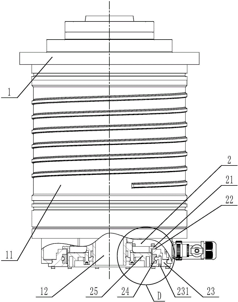
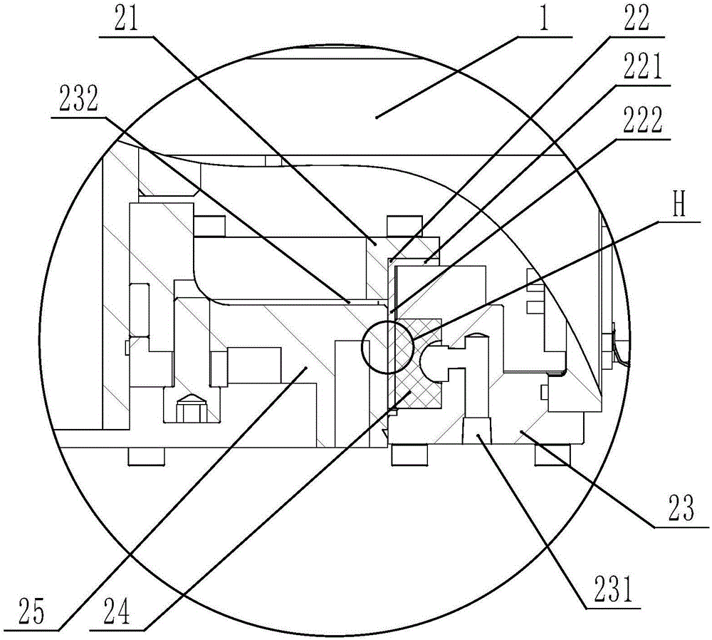
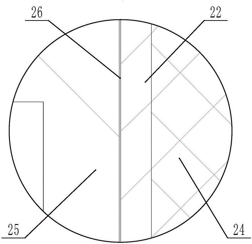
[0018] Preferred embodiments of the present invention are described below with reference to the accompanying drawings. Those skilled in the art should understand that these embodiments are only used to explain the technical principles of the present invention, and are not intended to limit the protection scope of the present invention. For example, although the specification and drawings describe the electric spindle hydraulic radial locking mechanism in the vertical direction, this is only for the convenience of description and does not affect the horizontal use of the electric spindle hydraulic radial locking mechanism. Personnel can adjust it as needed to suit the specific application. In practice, the electric spindle and the hydraulic radial locking mechanism of the electric spindle are usually arranged horizontally.

[0019] It should be noted that, in the description of the present invention, the terms "center", "upper", "lower", "left", "right", "vertical", "horizonta...


PUM


Abstract

The invention belongs to the field of motorized spindles, and particularly provides a motorized spindle hydraulic radial locking mechanism. The motorized spindle hydraulic radial locking mechanism aims to solving the problems that an existing motorized spindle locking device is complex to machine or assemble, and a motorized spindle moves axially when locked. The motorized spindle hydraulic radial locking mechanism comprises a flange, a hydraulic seat and a friction ring, wherein the hydraulic seat is fixed to the shell of the motorized spindle, the friction ring is arranged on the hydraulic seat, one end of the hydraulic seat is fixedly connected with the axial installation portion of the friction ring, the flange is fixedly connected with the rotary shaft of the motorized spindle, a hydraulic channel is formed in the other end of the hydraulic seat, hydraulic oil is fed into the hydraulic channel, and the hydraulic oil drives the axial friction portion of the friction ring to tightly press the flange so as to brake and lock the rotary shaft of the motorized spindle. According to the motorized spindle hydraulic radial locking mechanism, the structure of the motorized spindle locking device is simplified, the axial force applied to the motorized spindle when the motorized spindle is locked is eliminated, and therefore, the service life of the bearing on the motorized spindle is prolonged.

Description

technical field [0001] The invention belongs to the field of electric spindles, and specifically provides a hydraulic radial locking mechanism for electric spindles. Background technique [0002] As early as the 1950s, high-frequency electric spindles for grinding small holes appeared. At that time, the frequency converter used vacuum tubes. Although the speed was high, the transmitted power and torque were very small. With the demand for high-speed cutting and the advancement of electronic technology, inverters and vector control drives for all solid-state components emerged as the times require; coupled with the emergence of hybrid ceramic bearings, in the late 1980s and early 1990s, milling machines appeared. , turning machining centers, and in recent years, turning and milling compound electric spindles have become increasingly popular. The turning-milling compound electric spindle generally adopts the method of gear locking or external disc brake. The processing, assem...

Claims


Application Information

Patent Timeline
IPC IPC(8): B23Q5/52
CPCB23Q5/52
Inventor 项久鹏蒙七星
Owner BEIJING CTB SERVO CO LTD
Learn More