Plastic bottle compression mechanism

A technology of compression mechanism and plastic bottle, applied in the direction of presses, manufacturing tools, etc., can solve the problems of easy rebound, thick material, and rebound, and achieve the effect of not easy to rebound, avoid liquid splashing, and reduce driving force.

Inactive Publication Date: 2016-11-16
东莞市动能环保科技有限公司
View PDF7 Cites 4 Cited by
  • Summary
  • Abstract
  • Description
  • Claims
  • Application Information

AI Technical Summary

Problems solved by technology

Since the hardest part of the beverage bottle is the mouth and the bottom of the bottle, the material of these two parts is relatively thick, and it is not easy to squeeze or rebound after being squeezed. There will also be rebound after the compression, and the compression effect is not ideal; and the bottle material will be mixed when the spike array pierces the compression

Method used


Image

  • Plastic bottle compression mechanism
  • Plastic bottle compression mechanism
  • Plastic bottle compression mechanism

Examples


Embodiment Construction

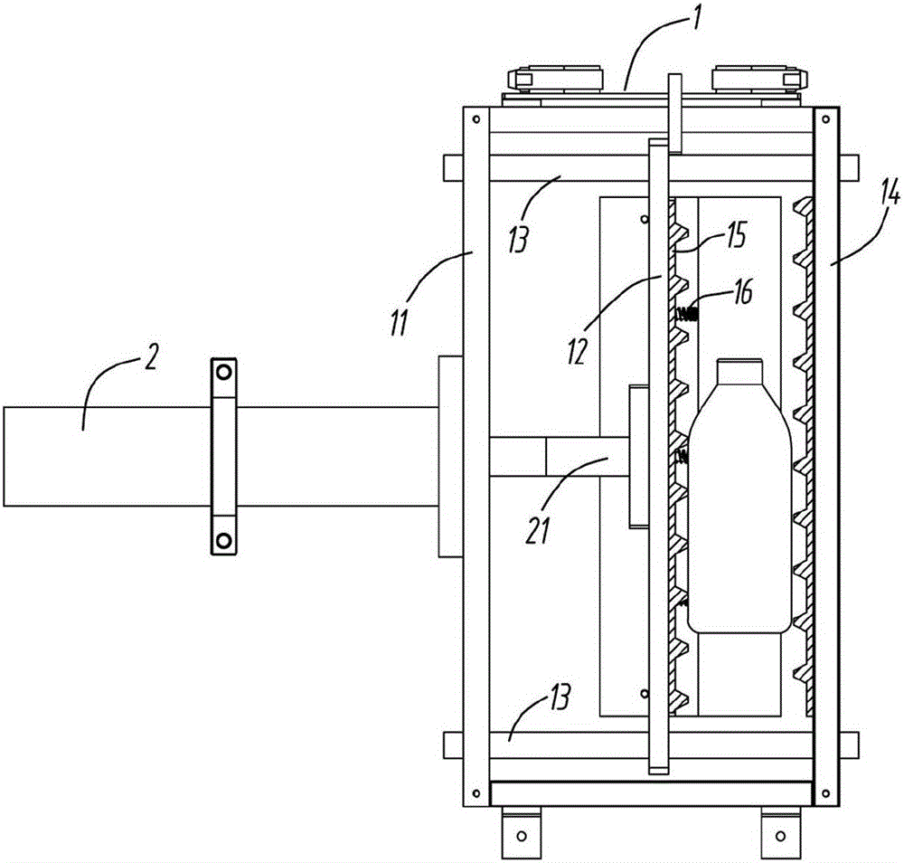
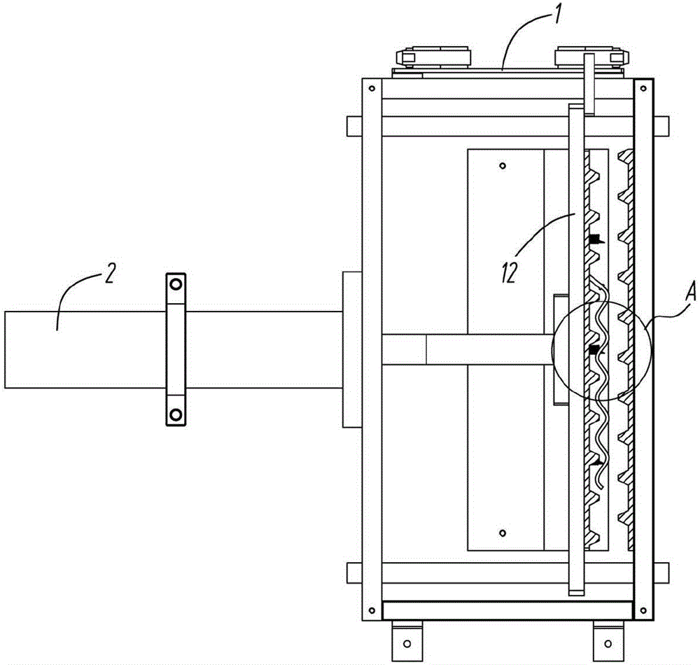
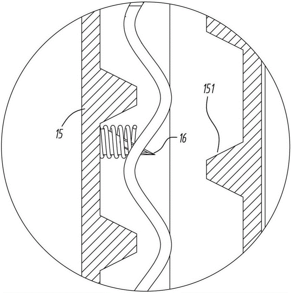
[0020] refer to Figure 1 to Figure 6 The plastic bottle compression mechanism shown includes a compression box 1, and the movable plate 12 parallel to the rear side plate 11 is arranged inside the compressed box 1, and the movable plate 12 can be driven by the hydraulic cylinder 2 to be relatively The rear side plate 11 is translated back and forth, the hydraulic cylinder 2 is fixed on the rear side plate 11 and the movable end 21 passes through the rear side plate 11 and is fixed to the movable plate 12 . The movable plate 12 is pierced with a number of guide posts 13 to keep its translation stability, and the guide posts 13 include four guide posts fixed between the front side plate 14 and the rear side plate 11 and evenly distributed at the four corners. . A rack plate 15 is provided on the inner wall between the movable plate 12 and the front side plate 14 of the compression box 1, and the rack plate 15 has vertical racks 151 evenly distributed. The cross section of the...


PUM


Abstract

The invention discloses a plastic bottle compression mechanism. The plastic bottle compression mechanism comprises a compression box body having a front side plate and a rear side plate and a moving plate which is driven by an oil pressure cylinder to translate, wherein the inner walls of the moving plate and the front side plate are provided with a rack plate, each rack plate is provided with vertical racks which are uniformly distributed, each rack is in a trapezoidal shape, a distance between two adjacent racks is greater than a maximum width of the rack, and the racks of the two rack plates are uniformly crossly distributed; one rack plate is provided with a vertical puncture needle, the puncture needle is in a hollow tubular shape, and a needle point is provided with a diagonal plane;the puncture needle is also sleeved with a spring. Two sides of the engaged racks are provided with a gap part, and the front part of a bottle opening can automatically fall into two adjacent racks of one rack plate, while a bottle body is alternately squeezed by two rack plates in two opposite directions, so that the bottle body is flatly attached to the gap parts and unlikely to bounce up; whenin squeezing, the tops of the two adjacent racks of the same rack plate form two supporting points, while the tops of the racks at the opposite side squeeze the bottle body from a middle point of thetwo supporting points, so that a driving force provided by the oil pressure cylinder can be reduced.

Description

technical field [0001] The invention relates to the technical field of beverage bottle recycling devices, in particular to a plastic bottle compression mechanism. Background technique [0002] At present, most of the beverage packaging bottles are made of PET, iron, aluminum and other materials. Whenever the weather is hot, the consumption of various beverages is very large, resulting in a large number of empty bottles. It takes a lot of human resources to deal with these empty bottles , and if this kind of disposable bottle cannot be recycled scientifically and effectively, it will continue to cause great pollution to the environment and cause continuous waste of resources; if it can be reasonably guided and scientifically recycled, materials such as PET, iron, and aluminum All can be recycled and reused, and have certain commercial value. [0003] Traditional recycling devices for plastic bottles generally include squeezing devices and cutting devices. Due to the high pow...

Claims


Application Information

Patent Timeline
Patent Type & Authority Applications(China)
IPC IPC(8): B30B9/30
CPCB30B9/321B30B9/3021B30B9/3032
Inventor 王乐新
Owner 东莞市动能环保科技有限公司
Why Eureka
Try Eureka