
Digital textile printer nozzle trolley structure and digital textile printer with nozzle trolley

A technology of digital printing machine and nozzle trolley, which is applied in printing, typewriter, transfer material, etc., and can solve the problems of low assembly efficiency and other issues

Inactive Publication Date: 2016-11-16
杭州彩悦图邦科技有限公司
View PDF23 Cites 3 Cited by
  • Summary
  • Abstract
  • Description
  • Claims
  • Application Information

AI Technical Summary

Problems solved by technology

[0003] The digital printing machine includes a nozzle trolley and a printing platform. The nozzle trolley is higher than the printing platform and is slidably connected to the slide rail for inkjet to the cloth. The nozzle trolley usually includes a nozzle and an outer bracket. The outer bracket Slidingly connected on the slide rail, the nozzle is installed on the outer bracket, the cloth is laid flat on the printing platform, and the printing platform will be equipped with a pressing component specially used for pressing the cloth, so the printing of the pattern on the cloth The quality is determined by the position of the nozzle, that is, the parallelism between the nozzle and the horizontal plane of the printing platform directly determines the printing quality on the pattern. When the digital printing machine is assembled at the factory, it is necessary to ensure the error of the parallelism between the nozzle and the horizontal plane of the printing platform. It must be within the range of millimeters. In the prior art, the printing platform is generally positioned and installed first, and the nozzle trolley is installed after the horizontal plane of the printing platform is installed according to the standard. For the precise distance between the nozzle trolley and the printing platform The accuracy is usually determined by the processing accuracy of the outer bracket of the nozzle trolley, the assembly accuracy of the nozzle and the outer bracket, and the assembly accuracy between the outer bracket and the slide rail. These factors often rely on the experience of the assembly workers in the assembly process. However, the experience of the assembly workers is an uncontrollable standard, and it cannot guarantee that each assembly can meet the standard smoothly. Therefore, it is often necessary to disassemble and re-correct during the overall installation process to meet the standard. This directly leads to low assembly efficiency.

Method used


Image

  • Digital textile printer nozzle trolley structure and digital textile printer with nozzle trolley
  • Digital textile printer nozzle trolley structure and digital textile printer with nozzle trolley
  • Digital textile printer nozzle trolley structure and digital textile printer with nozzle trolley

Examples


Embodiment 1

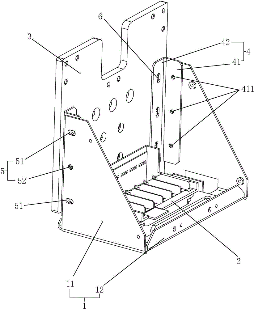
[0035] Embodiment one, such as figure 1 As shown, a nozzle trolley structure of a digital printing machine includes a back plate 3, a housing 1 and a nozzle 2, and the housing 1 further includes a bottom plate 12 and two side plates 11 integrally provided with the bottom plate 12. The casing 1 is made by bending a metal plate, and the spray head 2 is fixedly installed on the bottom plate 12 .

[0036] The side plate 11 is perpendicular to the back plate 3, an adjustment plate 4 is arranged between the side plate 11 and the back plate 3, and the adjustment plate 4 includes a first connecting plate 41 and a second connecting plate 41 arranged vertically to each other. The connecting plate 42 , the first connecting plate 41 is connected to the side plate 11 , and the second connecting plate 42 is connected to the back plate 3 .

[0037] The first connecting plate 41 is provided with at least two through holes 411 in the vertical direction. Here, two through holes 411 or three th...

Embodiment 2

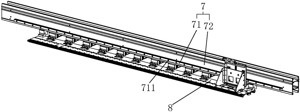
[0041] Embodiment two, such as Figure 2-Figure 3 As shown, a digital printing machine includes a printing platform 8 and a slide rail assembly 7. The slide rail assembly 7 includes a support beam 72 and a guide rail 71 connected to the support beam 72. The guide rail 71 is connected to the back Sliding connection is formed between the boards 3 through means such as sliders in the prior art.

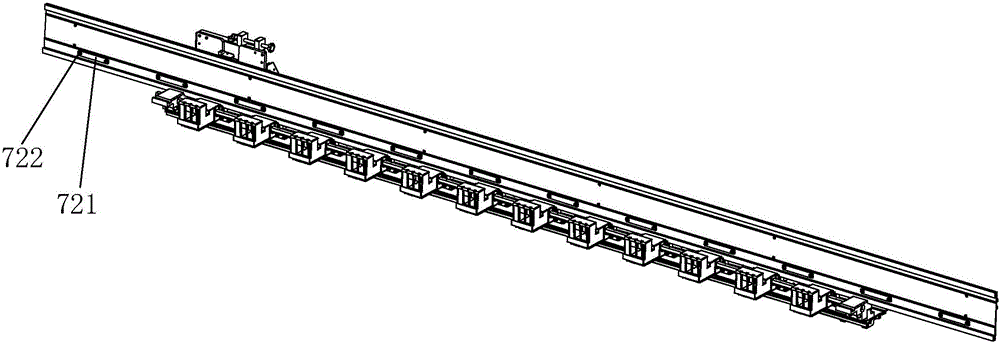
[0042] The supporting beam 72 is provided with a plurality of first positioning holes arranged at intervals, and the first positioning holes are arranged along the transverse direction, and the third positioning hole 711 matched with the first positioning holes is arranged on the described guide rail 71, so that The support beam 72 is provided with a backing plate 721 on the other side end surface relative to the guide rail 71, the backing plate 721 is arranged in a long waist shape, and the backing plate 721 is provided with at least two second positioning holes, The scheme of two seco...

Embodiment 3

[0046] Embodiment three, such as Figure 4-Figure 5 As shown, the difference between the third embodiment and the first embodiment lies in the moving structure 6. In this embodiment, the moving structure 6 includes a lifting block 61 arranged between the back plate 3 and the second connecting plate 42, two adjusting plates 4 The second connecting plate 42 is fixed to the lifting block 61 by bolts, and the two positions of the lifting block 61 corresponding to the second connecting plate 42 are provided with a guide column 64, and the two ends of the guiding column 64 are connected to the back plate 3 are connected by setting a fixed seat 63, the fixed seat 63 is fixed on the back plate 3 by bolts, the guide column 64 is axially positioned between the two fixed seats 63, and the lifting block 61 A spring 62 is arranged between the two fixing seats 63 , and the spring 62 is sheathed in the guide column 64 .

[0047] The middle position of the lifting block 61 is provided with a...


PUM


Abstract

The invention discloses a nozzle trolley structure of a digital printing machine, which includes a back plate, a casing and a nozzle. The casing includes two side plates and a bottom plate. The nozzle is fixed on the bottom plate. The adjusting plate, the adjusting plate includes a first connecting plate and a second connecting plate arranged at right angles, the first connecting plate and the side plate are hingedly connected and the casing can rotate around the hinge point, and the casing is provided with a The casing is fixed on the limit piece on the adjusting plate, and a moving structure is arranged between the second connecting plate and the back plate to drive the adjusting plate to move in the vertical direction, and at the same time discloses a digital printing machine with the nozzle trolley structure The purpose of the present invention is to provide a digital printing machine nozzle carriage structure and a high-precision digital printer that can improve installation efficiency while ensuring installation efficiency.

Description

technical field [0001] The invention relates to the technical field of spare parts of a digital printing machine, in particular to a structure and an installation method of a nozzle trolley of a digital printing machine. Background technique [0002] Digital printing machine is printing with digital technology. Digital printing technology is a high-tech product that integrates machinery, computer, electronic information technology and gradually formed with the continuous development of computer technology. [0003] The digital printing machine includes a nozzle trolley and a printing platform. The nozzle trolley is higher than the printing platform and is slidably connected to the slide rail for inkjet to the cloth. The nozzle trolley usually includes a nozzle and an outer bracket. The outer bracket Slidingly connected on the slide rail, the nozzle is installed on the outer bracket, the cloth is laid flat on the printing platform, and the printing platform will be equipped w...

Claims


Application Information

Patent Timeline
IPC IPC(8): B41J25/24B41J2/01B41J3/407
CPCB41J25/24B41J2/01B41J3/4078
Inventor 宣阳周新城
Owner 杭州彩悦图邦科技有限公司
Learn More