Eureka AIR delivers breakthrough ideas for toughest innovation challenges, trusted by R&D personnel around the world.

Composite unmanned helicopter

An unmanned helicopter, compound technology, applied in the field of aviation aircraft, can solve the problems affecting the life time and range of the helicopter, and achieve the effect of improving the life time and range

Inactive Publication Date: 2016-11-16
NANJING UNIV OF AERONAUTICS & ASTRONAUTICS
View PDF5 Cites 10 Cited by
  • Summary
  • Abstract
  • Description
  • Claims
  • Application Information

AI Technical Summary

Problems solved by technology

That is to say, in the existing technology, the tail rotor and the rotor do not work at the optimal speed, which affects the endurance time and range of the helicopter

Method used


Image

  • Composite unmanned helicopter
  • Composite unmanned helicopter
  • Composite unmanned helicopter

Examples


Embodiment Construction

[0020] In order to enable those skilled in the art to better understand the technical solutions of the present invention, the present invention will be further described in detail below in conjunction with the accompanying drawings and specific embodiments. Hereinafter, embodiments of the present invention will be described in detail, examples of which are shown in the accompanying drawings, wherein the same or similar reference numerals denote the same or similar elements or elements having the same or similar functions throughout. The embodiments described below by referring to the figures are exemplary only for explaining the present invention and should not be construed as limiting the present invention.

[0021] Those skilled in the art can understand that, unless otherwise defined, all terms (including technical and scientific terms) used herein have the same meaning as commonly understood by one of ordinary skill in the art to which this invention belongs. It should als...


PUM


Abstract

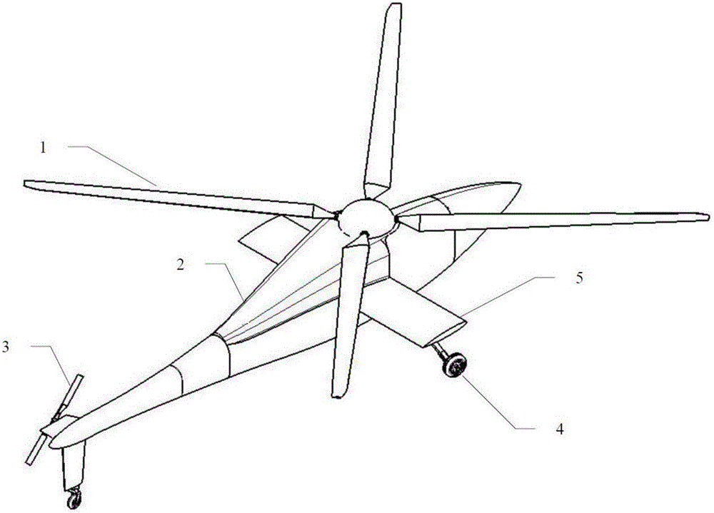
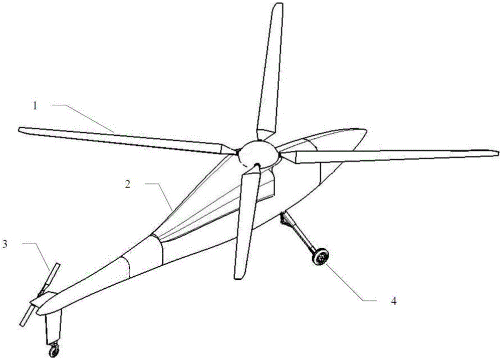
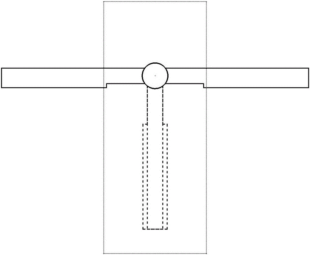
The embodiment of the invention discloses a composite unmanned helicopter and relates to the technical field of aviation aircrafts. Rotor wings and a tail rotor can be made to work at the optimal rotating speed, and the required power of the unmanned helicopter can be lowered to be the lowest. The composite unmanned helicopter comprises the rotor wings (1), a helicopter body (2), the tail rotor (3) and a landing gear (4), wherein the helicopter body (2) is provided with foldable wings (5) which are symmetrically mounted on the two sides of the helicopter body (2). The unfolding directions of the foldable wings are perpendicular to the axial direction of the helicopter body, and the connecting line between the pneumatic center of each foldable wing and the gravity center of the helicopter body is perpendicular to the axis of the helicopter body. The duration of flight and the air range of the helicopter can be effectively prolonged.

Description

technical field [0001] The invention relates to the technical field of aviation aircraft, in particular to a compound unmanned helicopter. Background technique [0002] The rotor of an unmanned helicopter can provide the helicopter with rising lift and forward pulling force at the same time. The rotor speed needs to be determined according to the maximum take-off weight of the helicopter. The designed rotor speed must ensure that the helicopter can fly normally at this take-off weight. However, the rotor speed of a conventional helicopter is fixed, which causes the helicopter rotor to work at the speed required for the maximum take-off weight under all take-off weights. Therefore, when the rotor speed is fixed, the helicopter rotor does not work at the maximum speed in most cases. Under the optimal speed, the power of the rotor increases, which limits the improvement of the performance of the helicopter. Tail rotors are similar to rotors in that a fixed rotational speed has...

Claims


Application Information

Patent Timeline
Patent Type & Authority Applications(China)
IPC IPC(8): B64C27/08B64C27/12B64C1/30
CPCB64C27/08B64C1/30B64C27/12
Inventor 韩东张勇刚
Owner NANJING UNIV OF AERONAUTICS & ASTRONAUTICS
Why Eureka
Eureka Blog
Learn More