Movable joint of flat-wall pipe

A movable joint, flat wall technology, applied in the direction of pipe/pipe joint/pipe fitting, pipe, branch pipeline, etc., can solve the problem of inability to ensure the stability of the connection between the joint and the wellbore, achieve locking function guarantee, improve stability, Easy to install effect

Active Publication Date: 2016-11-16
浙江联塑科技实业有限公司
View PDF7 Cites 2 Cited by
  • Summary
  • Abstract
  • Description
  • Claims
  • Application Information

AI Technical Summary

Problems solved by technology

The main body of the disclosed joint extends from the outer wall of the inspection well to the inner wall, which greatly reduces the difficulty of construction and improves work efficiency; however, the joint of this structure is installed from the outside to the inside, which is suitable for water supply. If the water pressure in the wellbore is too high or the application When draining water, the direction of water pressure from the inside to the outside cannot guarantee the stability of the connection between the joint and the wellbore, as well as the tightness of the connection between the joint and the wellbore

Method used


Image

  • Movable joint of flat-wall pipe
  • Movable joint of flat-wall pipe
  • Movable joint of flat-wall pipe

Examples


Embodiment 1

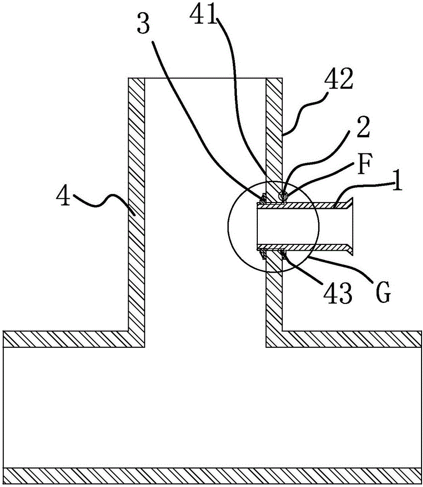
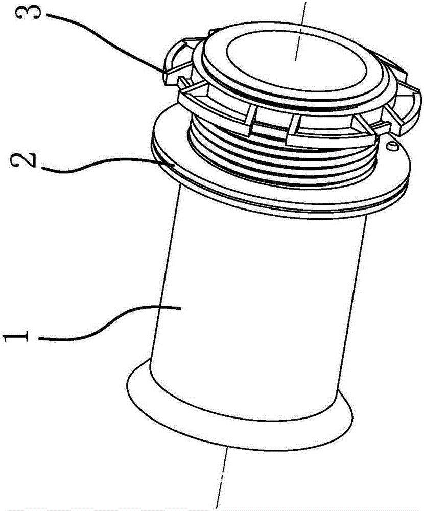
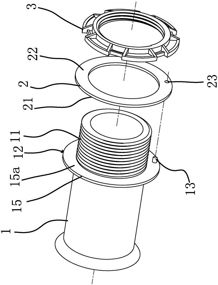
[0049] Such as figure 1 , 2 , 3, 11, and 16, the joint body 1 of the present invention is a middle-pass structure, one end of the joint body 1 is provided with an external thread 11, and the middle part of the joint body 1 has a radially outwardly protruding collar 15, the collar 15 has an annular end surface 15a, and the external thread 11 extends to the annular end surface 15a; the positioning surface 12 of the present invention is the annular end surface 15a on the collar 15 . The end face of the collar 15 protruding from the joint body 1 is ring-shaped. On the one hand, the ring-shaped end face 15a is used as a positioning surface for positioning the sealing ring 2 and acting as an external seal after the movable joint of the present invention is connected; The termination surface of the external thread 11 on the joint body 1 . The positioning surface 12 is provided with a positioning column 13 parallel to the axis of the external thread 11 , the positioning column 13 ex...

Embodiment 2

[0064] Such as Figure 5 , 8 , 12, the structure of this embodiment is similar to that of Embodiment 1, the difference is that the angle formed between the dividing surface 39a and the inner surface of the lock nut 3 in the present invention is less than 90 degrees, and this setting can be used in dividing The retaining surface 1 39a preferably acts on the external thread 11 of the joint body 1 after being stressed, thereby improving the sealing performance between the inner side of the lock nut 3 and the joint body 1 . In the present invention, the angle between the second dividing surface 39b and the locking surface 31 is 90 degrees, which is convenient for the processing of the locking nut 3 .

Embodiment 3

[0066] Such as Figure 6 , 9 , 13, the structure of this embodiment is similar to that of Embodiment 1, the difference is that the angle formed by the dividing surface 39a and the inner surface of the lock nut 3 in the present invention is equal to 90 degrees, which is convenient for locking Nut 3 is machined. The included angle between the second dividing surface 39b and the locking surface 31 in the present invention is less than 90 degrees. This setting can better act on the inner wall 41 when the second dividing surface 39b is stressed, thereby improving the locking surface 31 and the inner wall. 41 tightness.


PUM


Abstract

The invention provides a movable joint of a flat-wall pipe, and belongs to the technical field of mechanical engineering or buildings. The movable joint solves the technical problems that existing pipe joints are complex in structure and poor in sealing performance. The movable joint comprises a joint body with an external thread at one end, and a seal ring and a locking nut are connected to the end, provided with the external thread, of the joint body in a sleeving mode, and a locating surface extending outwards in the radial direction of the joint body is arranged in the middle of the joint body and is provided with locating columns parallel with the axis of the external thread; the seal ring is provided with locating holes parallel with the axis, and the locating columns penetrate through the locating holes and extend into the seal ring; and the seal ring is arranged between the locating surface and the locking nut and is attached to the locating surface. According to the movable joint, the external-to-internal self-locating structure and the sealing mode combining external sealing and internal sealing are adopted, the structure is simple, the connection stability is good and the sealing performance is good.

Description

technical field [0001] The invention belongs to the technical field of mechanical engineering or construction, and relates to a pipe joint, in particular to a movable joint of a flat-wall pipe. Background technique [0002] Inspection wells are set up for the convenience of maintenance and installation of power supply, water supply, drainage, sewage discharge, communication, cable TV, gas pipes, street lamp lines, etc. of urban underground infrastructure; they are generally located at pipeline intersections, turnings, pipe diameters or slopes Changes, as well as at certain distances on straight pipe sections, are ancillary structures that facilitate regular inspections. [0003] With the rapid development of urbanization, the application of inspection wells is becoming more and more extensive. According to the number and angle of connections, there are straight-through wells, three-way wells, four-way wells, and 90-degree elbow wells. In order to adapt to various drainage c...

Claims


Application Information

Patent Timeline
Patent Type & Authority Applications(China)
IPC IPC(8): F16L41/10
CPCF16L41/10
Inventor 叶后富
Owner 浙江联塑科技实业有限公司
Why Eureka
Try Eureka