Three-shaft adjusting hanging arm joint for hanging projector

A technology for projectors and arm joints, applied in the direction of supporting machines, mechanical equipment, machine tables/brackets, etc., can solve problems such as positioning damage, affecting positioning stability and reliability, and difficult to adjust, achieving good stability and Shock resistance, beneficial to product upgrading, and the effect of large worm transmission ratio

Inactive Publication Date: 2016-11-16
LIUZHOU CHANGHONG MACHINE MFG
View PDF6 Cites 7 Cited by
  • Summary
  • Abstract
  • Description
  • Claims
  • Application Information

AI Technical Summary

Problems solved by technology

[0005] 1. The adjustment process consumes more labor;
[0006] 2. Angle positioning is adjusted by hand to overcome the static friction of the shaft end, and the accuracy is poor;
[0007] 3. The adjustment process is cumbersome, time-consuming, and relies too much on the experience of the operator, especially the degree of locking of the locking bolts at the end of the coarse adjustment step is difficult to grasp. The static friction that needs to be generated just balances the gravity of the projector. If it is too tight, use If the hand is too loose, it will be difficult to move and adjust, and if it is too loose, the positioning will be unstable, which will bring a lot of repetitions to the actual adjustment process;
[0008] 4. In long-term suspension, the fatigue of the bolt material or the corrosion of the friction surface may affect the stability and reliability of the positioning. In case of unexpected impact and shaking, the original positioning is easily destroyed and the adjusted angle will be changed.

Method used


Image

  • Three-shaft adjusting hanging arm joint for hanging projector
  • Three-shaft adjusting hanging arm joint for hanging projector
  • Three-shaft adjusting hanging arm joint for hanging projector

Examples


Embodiment Construction

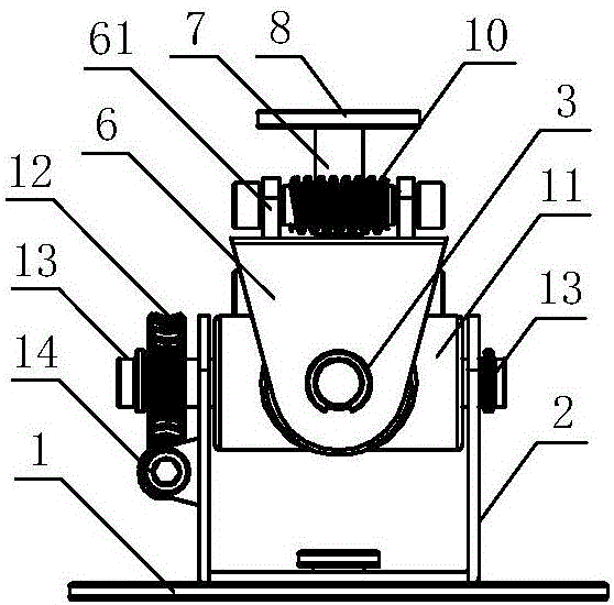
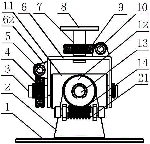
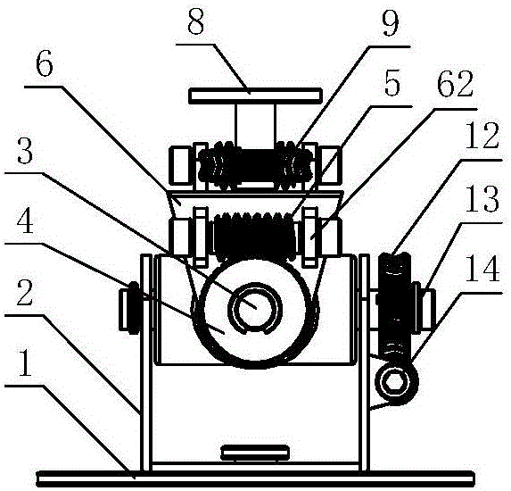
[0030] A three-axis adjustable arm joint for suspending a projector, comprising an arm fixing plate 8 and a projector fixing plate 1;

[0031] The hanging arm fixing plate 8 is connected with the projector fixing plate 1 through a three-axis adjustment mechanism, and the three-axis adjustment mechanism includes an upper U-shaped frame 6, a lower U-shaped frame 2, and an upper / lower U-shaped frame. The X-axis adjustment assembly, the Y-axis adjustment assembly and the Z-axis adjustment assembly;

[0032] The X-axis adjustment assembly includes an X-axis 13, an X-axis gear 12 and an X-axis worm 14,

[0033] The Y-axis adjustment assembly includes a Y-axis 3, a Y-axis gear 4 and a Y-axis worm 5,

[0034] The Z-axis adjustment assembly includes a Z-axis 7, a Z-axis gear 9 and a Z-axis worm 10;

[0035] The upper U-shaped frame 6 is connected to the lower U-shaped frame 2 through a cross shaft assembly, and the centers of the two vertical axes of the cross shaft assembly are resp...


PUM


Abstract

Disclosed is a three-shaft adjusting hanging arm joint for hanging a projector. The three-shaft adjusting hanging arm joint comprises a hanging arm fixing disk, a projector fixing disk and a three-shaft adjusting mechanism. The three-shaft adjusting mechanism comprises an upper U-shaped frame, a lower U-shaped frame, an X-shaft adjusting assembly, a Y-shaft adjusting assembly and a Z-shaft adjusting assembly, wherein the X-shaft adjusting assembly, the Y-shaft adjusting assembly and the Z-shaft adjusting assembly are installed in the upper / lower U-shaped frame. The upper U-shaped frame and the lower U-shaped frame are connected through an X-shaft and a Y-shaft, wherein the X-shaft and the Y-shaft are arranged on a cross-shaped rotating shaft assembly and are perpendicular to each other. The X-shaft adjusting assembly is installed on one side of the upper U-shaped frame, the Y-shaft adjusting assembly is installed on one side of the lower U-shaped frame, the lower U-shaped frame is connected with the projector fixing disk, the Z-shaft adjusting assembly is installed on the top surface of the upper U-shaped frame, and a Z-shaft of the Z-shaft adjusting assembly is fixedly connected with the hanging arm fixing disk. The three-shaft adjusting hanging arm joint has good stability and impact resistance, angle adjustment is accurate, adjustment is easy, convenient, rapid and accurate and saves labor, and self-locking positioning can be achieved.

Description

technical field [0001] The invention relates to a hanging joint, in particular to a three-axis adjusting hanging arm joint for hanging a projector. Background technique [0002] When installing the projector, in order not to occupy the ground space, most projector users will choose to hang the projector or wall-mount the installation method, both of which require a special projector rack, in order to ensure a The directional projection image can be accurately projected to the designated position. The requirement for the projector hanger is that it has a three-axis adjustment function, that is, the X-axis adjusts the pitch angle, the Y-axis adjusts the horizontal rotation angle, and the Z-axis adjusts the left-right tilt angle. The adjustment of the three axes must have considerable precision and stability, otherwise it will cause the projection image to shift and deform, which will affect the image quality. [0003] At present, the arm joints of the common projector racks m...

Claims


Application Information

Patent Timeline
Patent Type & Authority Applications(China)
IPC IPC(8): F16M13/02F16M11/12G03B21/56
CPCF16M13/02F16M11/123G03B21/56
Inventor 何圣
Owner LIUZHOU CHANGHONG MACHINE MFG
Why Eureka
Try Eureka