A novel bifurcation diagram drawing method suitable for a sliding mode variable structure control inverter
A sliding mode variable structure and inverter technology, which is used in instruments, special data processing applications, single-network parallel feeding arrangements, etc. question
- Summary
- Abstract
- Description
- Claims
- Application Information
AI Technical Summary
Problems solved by technology
Method used
Image
Examples
Embodiment 1
[0086] Using the traditional inverter bifurcation diagram drawing method: first select a certain parameter as the bifurcation parameter, and in the case of a certain bifurcation parameter, select an initial value of the inductance current i of the state quantity of the inverter and substitute it into the discrete iterative equation to start the iteration ; Remove the transition process, and continuously sample the value of the state quantity at the same fixed sampling position for multiple sine cycles to obtain a set of steady state values. The bifurcation diagram of the inverter can be obtained by plotting the bifurcation parameter as the horizontal axis and the set of steady-state values under the bifurcation parameter as the vertical axis.
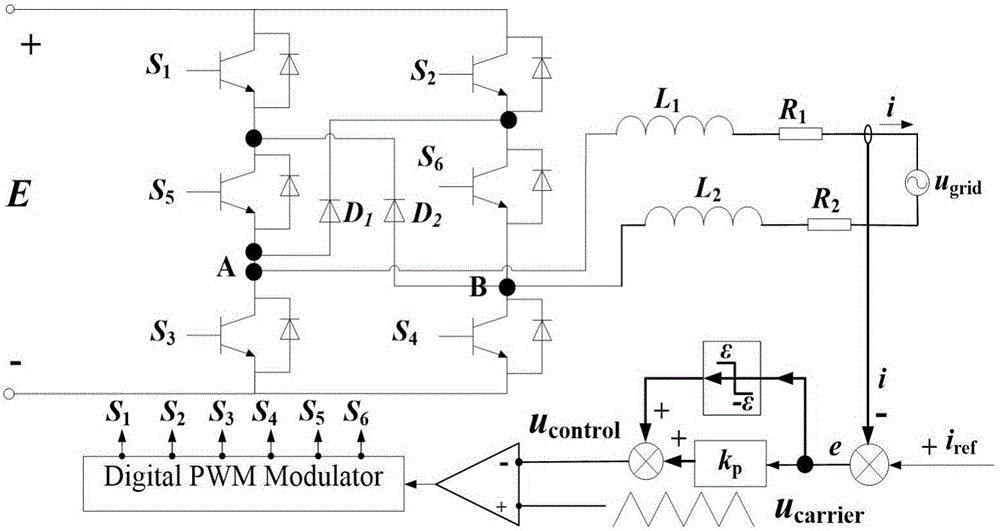
[0087] Select the circuit parameters as follows: E=400V, R 1 =R 2 = R = 2Ω, L 1 =L 2 =L=6.85mH,f 1 = 50Hz, i ref =I ref ×sin(100πt)A, I ref =5A,f s = 5kHz,k p = 0.2. N points are sampled per sine cycle, where N=f s / f 1 =5...
Embodiment 2
[0091] SMC is used to control the NGI-H6 system experimental prototype, and the parameters of the prototype are: E=400V, u grid frequency f ac = 50Hz, R 1 =R 2 = R = 10Ω, L 1 =L 2 =L=6.85mH, CNC chip: DSP2812, switching frequency f s =5kHz, the power grid is simulated by Chroma AC source. Taking different ε as an example, the experimental waveform of i is obtained.
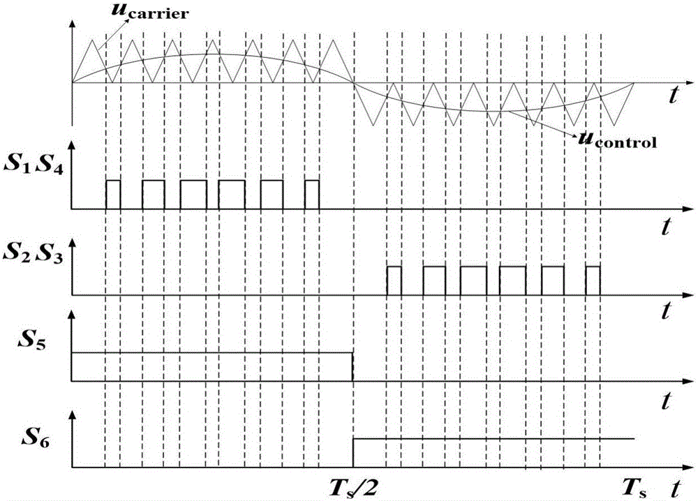
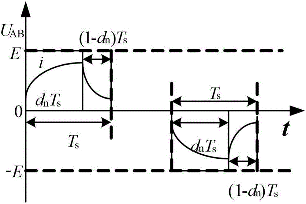
[0092] The principle of inverter state mutation point generation is: error signal e=iref -i, when the system error signal e appears in the nth switching cycle e(n)=i ref (n)-i(n)control (n)=-ε+k p ×e(n)control (n)carrier (n), so the duty cycle d n will suddenly become 0, and the inductor current will drop sharply, resulting in e(n+1)=i in (n+1) switching cycles ref (n+1)-i(n+1)>0, u control (n)=-ε+k p ×e(n)>0, u carrier (n+1) and u control (n+1) must have two intersections, the duty of the n+1th switching cycle d n+1 >0; therefore, in the positive half-period decline period of the inductor current, t...
PUM
 Abstract
Description
Claims
Application Information
 - R&D
- Intellectual Property
- Life Sciences
- Materials
- Tech Scout
- Unparalleled Data Quality
- Higher Quality Content
- 60% Fewer Hallucinations
Browse by: Latest US Patents, China's latest patents, Technical Efficacy Thesaurus, Application Domain, Technology Topic, Popular Technical Reports.
© 2025 PatSnap. All rights reserved.Legal|Privacy policy|Modern Slavery Act Transparency Statement|Sitemap|About US| Contact US: help@patsnap.com


