A Novel Bifurcation Diagram Drawing Method Applicable to Sliding Mode Variable Structure Control Inverters
A sliding mode variable structure and inverter technology, which is applied in the direction of instruments, special data processing applications, AC network circuits, etc., can solve the problems of not responding to system dynamic behavior and bifurcation phenomena, and drawing bifurcation diagrams, etc.
- Summary
- Abstract
- Description
- Claims
- Application Information
AI Technical Summary
Problems solved by technology
Method used
Image
Examples
Embodiment 1
[0086] Using the traditional inverter bifurcation diagram drawing method: first select a certain parameter as the bifurcation parameter, and in the case of a certain bifurcation parameter, select an initial value of the inductance current i of the state quantity of the inverter and substitute it into the discrete iterative equation to start the iteration ; Remove the transition process, and continuously sample the value of the state quantity at the same fixed sampling position for multiple sine cycles to obtain a set of steady state values. The bifurcation diagram of the inverter can be obtained by plotting the bifurcation parameter as the horizontal axis and the set of steady-state values under the bifurcation parameter as the vertical axis.
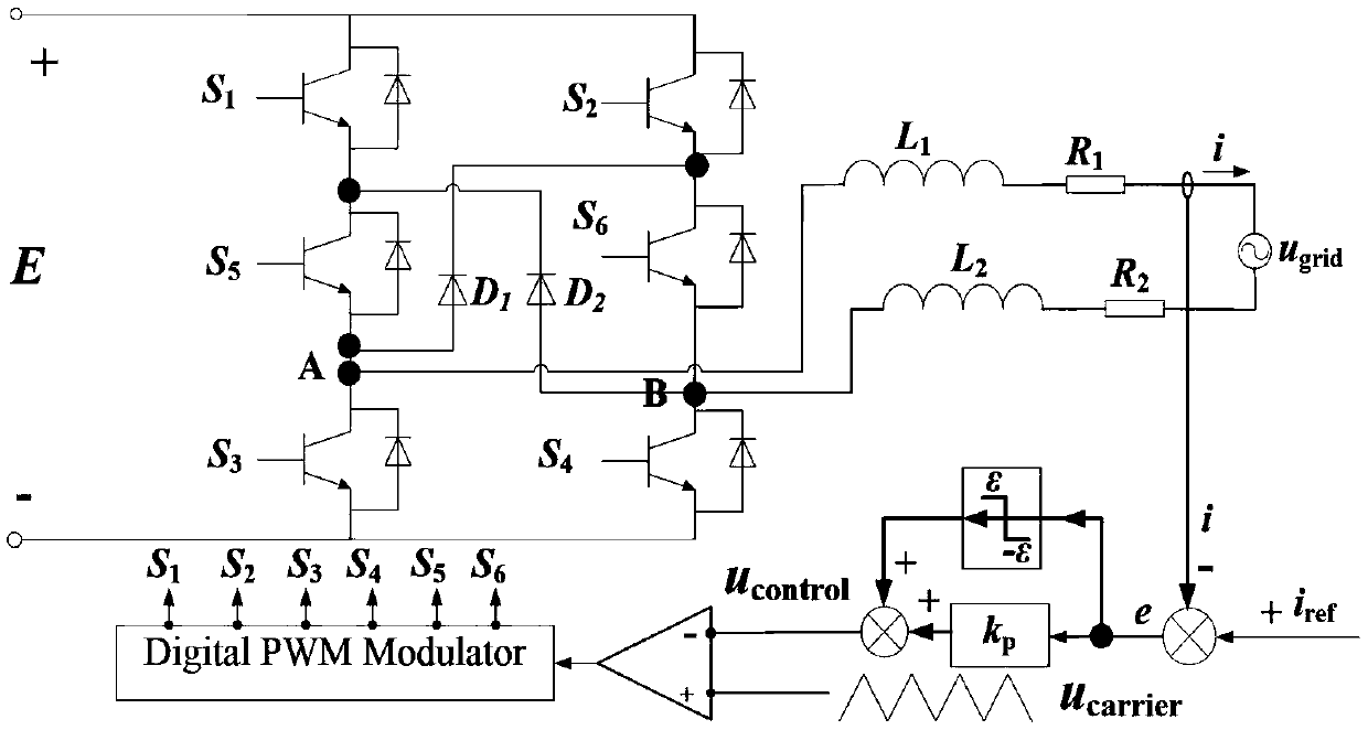
[0087] Select the circuit parameters as follows: E=400V, R 1 =R 2 = R = 2Ω, L 1 = L 2 =L=6.85mH,f 1 = 50Hz, i ref = I ref ×sin(100πt)A,I ref =5A,f s = 5kHz,k p = 0.2. N points are sampled per sine cycle, where N=f s / f 1 =...
Embodiment 2
[0091] SMC is used to control the experimental prototype of NGI-H6 system, and the parameters of the prototype are: E=400V, u grid frequency f ac = 50Hz, R 1 =R 2 = R = 10Ω, L 1 = L 2 =L=6.85mH, CNC chip: DSP2812, switching frequency f s=5kHz, the power grid is simulated by Chroma AC source. Taking different ε as an example, the experimental waveform of i is obtained.
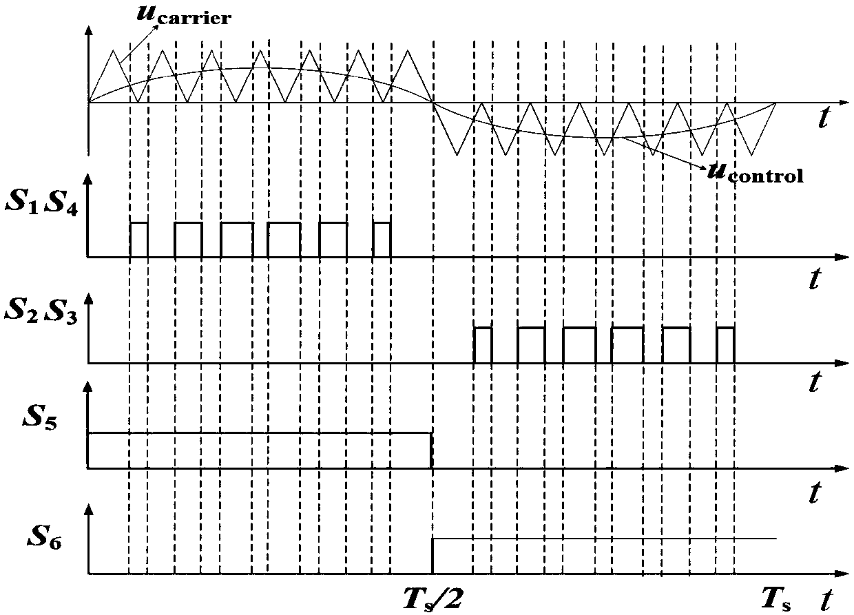
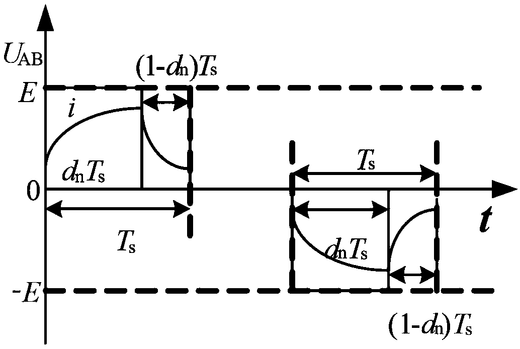
[0092] The principle of inverter state mutation point generation is: error signal e=i ref -i, when the system error signal e appears in the nth switching cycle e(n)=i ref (n)-i(n)control (n)=-ε+k p ×e(n)control (n)carrier (n), so the duty cycle d n will suddenly become 0, and the inductor current will drop sharply, resulting in e(n+1)=i in (n+1) switching cycles ref (n+1)-i(n+1)>0, u control (n)=-ε+k p ×e(n)>0,u carrier (n+1) and u control (n+1) must have two intersections, the duty of the n+1th switching cycle d n+1 >0; therefore, in the positive half-period decline period of the inductor curren...
PUM
 Abstract
Description
Claims
Application Information
 - R&D
- Intellectual Property
- Life Sciences
- Materials
- Tech Scout
- Unparalleled Data Quality
- Higher Quality Content
- 60% Fewer Hallucinations
Browse by: Latest US Patents, China's latest patents, Technical Efficacy Thesaurus, Application Domain, Technology Topic, Popular Technical Reports.
© 2025 PatSnap. All rights reserved.Legal|Privacy policy|Modern Slavery Act Transparency Statement|Sitemap|About US| Contact US: help@patsnap.com


