Supercharge Your Innovation With Domain-Expert AI Agents!

Low-voltage ground wire device

A ground wire, low voltage technology, applied in the field of low voltage ground wire devices, to achieve the effect of effective and rapid adjustment and reduction of difficulty

Inactive Publication Date: 2016-11-16
JINAN LICHENG POWER SUPPLY CO OF STATE GRID SHANDONG ELECTRIC POWER CO +1
View PDF4 Cites 4 Cited by
  • Summary
  • Abstract
  • Description
  • Claims
  • Application Information

AI Technical Summary

Problems solved by technology

[0006] In order to overcome the problems existing in the prior art, the present invention provides a compact low-voltage grounding wire. The angle of the insulating rod of this kind of grounding wire is adjustable, the length and volume are adjustable, and the clamp is firmly fixed, which avoids the traditional low-voltage grounding wire. timing problem

Method used


Image

  • Low-voltage ground wire device
  • Low-voltage ground wire device
  • Low-voltage ground wire device

Examples


Embodiment 1

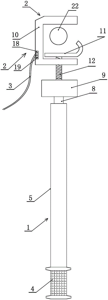
[0036] Embodiment one, such as Figure 5 As shown, the movable clamping part is a J-shaped plate, and the J-shaped plate is placed horizontally, wherein the horizontal part 14 of the J-shaped plate is fixed to the busbar 22 to be hung, and the curved part 15 of the J-shaped plate is the limit department.

Embodiment 2

[0037] Embodiment two, such as Figure 6 As shown, the movable clamping part is an L-shaped plate, and the L-shaped plate is placed horizontally, wherein the horizontal part 16 of the L-shaped plate is fixed to the busbar to be hung, and the vertical part 17 of the L-shaped plate is the limit department.

Embodiment 3

[0038] Embodiment three, such as Figure 7 As shown, the upper surface of the horizontal part of the J-shaped plate or the horizontal part of the L-shaped plate is provided with a serrated tooth shape, and the inner side above the fixed wire clamp body is matched with the horizontal part of the J-shaped plate or the horizontal part of the L-shaped plate. The surface of the busbar is also provided with a sawtooth profile 21 . The serrated tooth type can more firmly bite the busbar, fix it more firmly, prevent false hanging, improve safety, and avoid potential safety hazards.

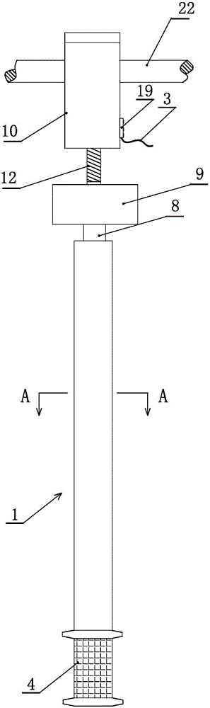
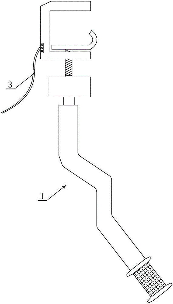
[0039] An annealed copper wire 3 is arranged on one side of the fixed wire clip body, and the annealed copper wire is fixed on the fixed wire clip body by a fixed card 18 and a screw 19, and the annealed copper wire is grounded.

[0040] Such as Figure 8 and Figure 9 As shown, in order to improve the bending effect, the insulating rod body is uniformly provided with a set of corrugated notches 20 arr...


PUM


Abstract

The invention discloses a low-voltage grounding wire device, which includes an insulating operating rod, a wire clamp and an annealed copper wire; wherein the insulating operating rod is a rod body that can be bent at any angle, which avoids the limitation of the space when hanging, reduces the Difficulty in working in space prevents the insulation rod from leaking out of the switch cabinet due to the inability to bend it, causing the cabinet door to fail to close. In addition, the angular position of the insulating rod can be adjusted arbitrarily according to the requirements of the actual operating space and position, so as to prevent it from being obstructed or obstructed by other objects or busbars during the operation. By setting the limit part and the serrated tooth shape on the wire clip, the wire clip and the hanging busbar are firmly fixed, preventing false hanging, improving safety, and avoiding potential safety hazards.

Description

technical field [0001] The invention relates to the technical field of grounding wires, in particular to a low-voltage grounding wire device. Background technique [0002] There are deficiencies in the installation of traditional low-voltage grounding wires: [0003] (1) The structure of the insulating operation rod and the clamp is fixed, and it will be limited by the space when it is hung. Cabinet door cannot be closed. [0004] (2) When the grounding wire is hung, due to reasons such as the angle and the technical design of the grounding wire, the contact position of the conductive end is not in full contact, which will cause poor contact or even false hanging, which has certain potential safety hazards. [0005] (3) The metal part of the commonly used grounding wire clamp is too large, and the phase-to-phase distance of the current low-voltage complete power distribution device is very small, and even the distance between adjacent busbars is very small. It may acciden...

Claims


Application Information

Patent Timeline
IPC IPC(8): H01G11/26H02G1/02
CPCY02E60/13H01G11/26H02G1/02
Inventor 李现魁杨茂林田克忠李希玉李孝荣赵士猛
Owner JINAN LICHENG POWER SUPPLY CO OF STATE GRID SHANDONG ELECTRIC POWER CO
Features
  • R&D
  • Intellectual Property
  • Life Sciences
  • Materials
  • Tech Scout
  • Unparalleled Data Quality
  • Higher Quality Content
  • 60% Fewer Hallucinations
Learn More