

Compact low-voltage grounding wire
A compact, grounding wire technology, applied in the direction of electrical connection sockets, overhead lines/cable equipment, etc., to reduce difficulty and avoid space restrictions
- Summary
- Abstract
- Description
- Claims
- Application Information
AI Technical Summary
Problems solved by technology
Method used
Image

Examples
no. 1 example
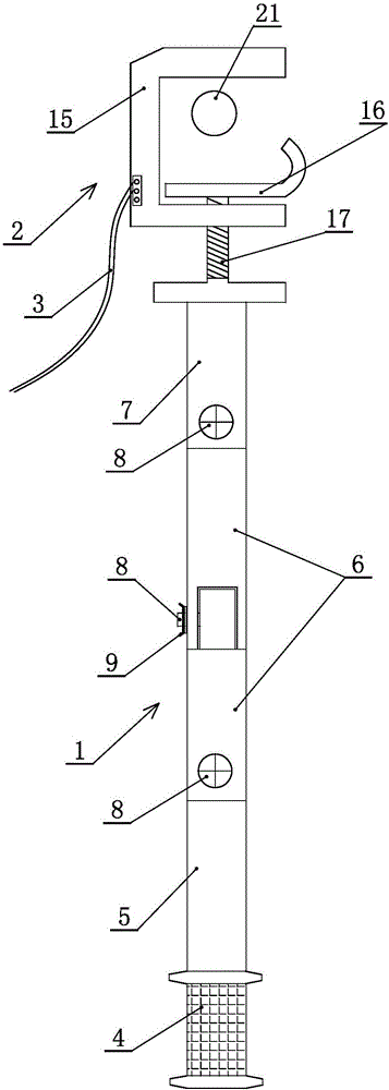
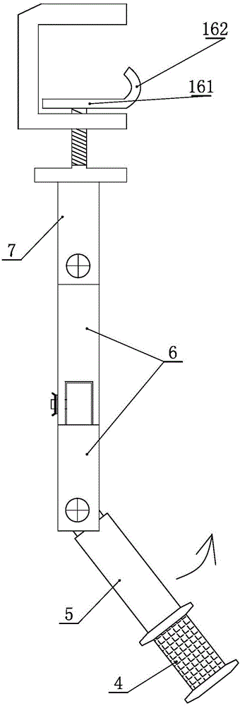
[0042] The first embodiment: as Figure 6 As shown, the movable clamping part is a J-shaped plate, and the J-shaped plate is placed horizontally, wherein the horizontal part 161 of the J-shaped plate is fixed to the busbar to be hung, and the curved part 162 of the J-shaped plate is the limit part.
no. 2 example
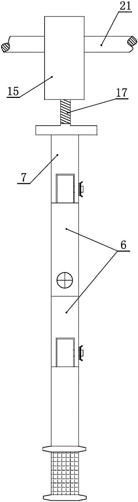
[0043] The second embodiment: as Figure 7 As shown, the movable clamping part is an L-shaped plate, and the L-shaped plate is placed horizontally, wherein the horizontal part 163 of the L-shaped plate is fixed to the busbar to be hung, and the vertical part 164 of the L-shaped plate is the The limit part described above.
[0044] The upper surface of the horizontal part of the J-shaped plate or the horizontal part of the L-shaped plate is provided with a sawtooth profile 19, and the busbar is fixed on the top of the fixed line clamp body with the horizontal part of the J-shaped plate or the horizontal part of the L-shaped plate. There are also serrated teeth on the surface.
no. 3 example
[0045] The third embodiment: as Figure 8 As shown, the upper side of the fixed wire clamp body close to its opening is provided with a downwardly extending limiting block 20, and the described limiting block cooperates with the described limiting part to realize the alignment between the wire clamp and the hanging female. Row 21 is firmly fixed.
[0046] By setting the limiting part on the movable clamping part of the wire clamp and setting the serrated teeth on the movable clamping part and the corresponding clamping part, setting a limiting block on the side close to the opening above the fixed wire clamp body, and the positioning block and the limiting The combination of the parts realizes the firm fixing of the wire clip and the hanging busbar, prevents false hanging, improves safety, and avoids potential safety hazards.
PUM
 Abstract
Description
Claims
Application Information