Supercharge Your Innovation With Domain-Expert AI Agents!

Variable-track single-axle excitation vibrator

A vibrator, variable technology, applied in the direction of the fluid that utilizes vibration, can solve the problems of many institutional consumables, error-prone, and inconvenient adjustment of the direction angle, etc., to achieve the adjustment of the vibration direction angle, convenient use and maintenance, and screening ideal effect

Inactive Publication Date: 2012-07-11
YIWU BLACK AND WHITE MINING MACHINERY
View PDF6 Cites 2 Cited by
  • Summary
  • Abstract
  • Description
  • Claims
  • Application Information

AI Technical Summary

Problems solved by technology

But the disadvantages are complex structure, high manufacturing cost and high power consumption
Moreover, when adjusting the direction angle of a three-axis vibrator (including a biaxial vibrator), it is necessary to open the vibrator to disassemble and assemble the ring gear (that is, by adjusting the eccentric phase angle difference of each excitation axis), which is very inconvenient. It is up to the user Error prone to self-tuning
[0006] The biggest shortcoming of the existing technology is that basically a vibrator can only realize one kind of movement trajectory, but cannot realize the conversion between different movement paths in the same device
[0007] To sum up, in the prior art, although the single-axis vibrator is simple in structure, it must be placed obliquely, which greatly reduces the screening effect, and the high and low ends of the vibrating box have a large drop, occupying more space and Increased installation costs; multi-axis exciters can be placed horizontally and improve the effect of excitation, but the mechanism consumes a lot of materials, making it difficult to manufacture (that is, high operating costs), and it is inconvenient to adjust the direction angle; the largest The disadvantage is that different motion trajectories cannot be selected in the same mechanism

Method used


Image

  • Variable-track single-axle excitation vibrator
  • Variable-track single-axle excitation vibrator
  • Variable-track single-axle excitation vibrator

Examples


Embodiment 1

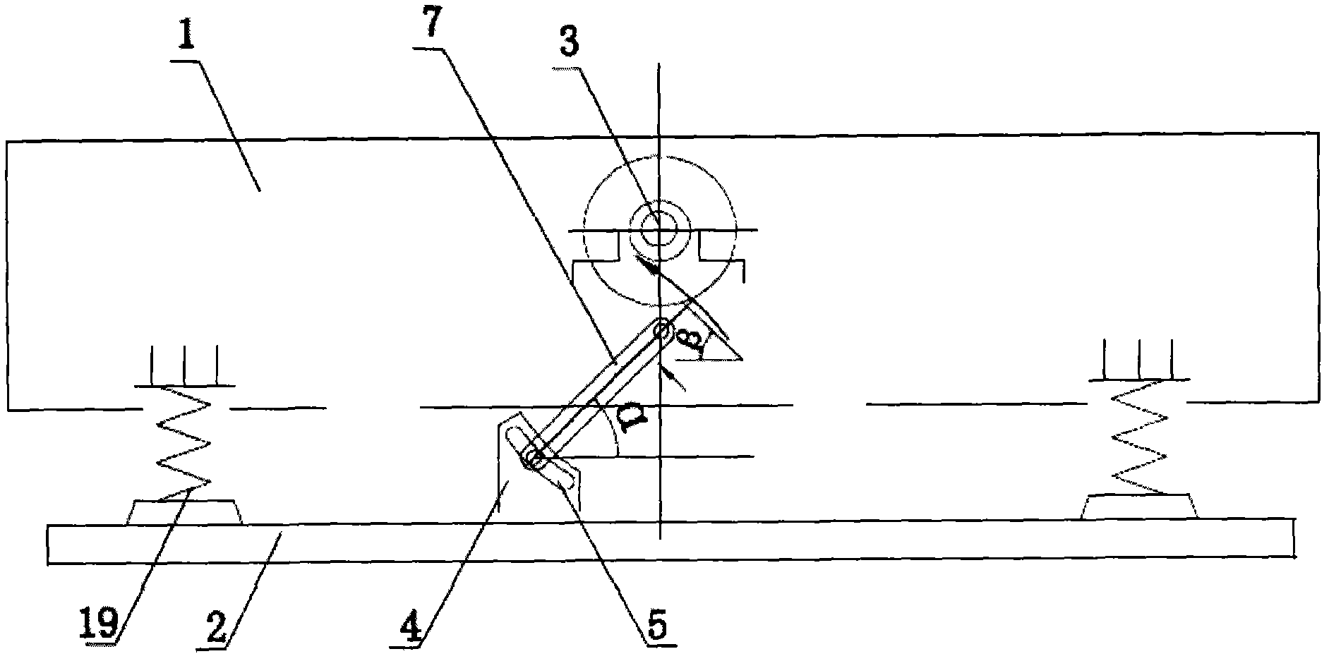
[0044] Embodiment 1: as figure 1 As shown, a single-axis variable trajectory vibrator includes a vibration box 1, a base 2 and an excitation shaft 3. The vibration axis 3 is arranged on the vibration box 1, and the vibration box 1 and the base 2 Buffer springs 19 are arranged on the four corners.

[0045] Between the vibration box 1 and the base 2, there is also an obliquely arranged rail 7. The rail 7 is a pair and symmetrically arranged on both sides of the vibration box 1. The length of the rail 7 is non-adjustable. fixed rod.

[0046] The hinge shaft between the lower end of the track rod 7 and the base 2 is arranged in the arc slot 5 and locked by the adjusting nut; the arc slot 5 is arranged on the base 4, and the base 4 is arranged on the base 2.

[0047] The rail-fixing rod 7 is arranged perpendicular to the fixed axis of the excitation shaft 3, and the hinge shaft between the upper end of the rail-fixing rod 7 and the vibration box 1 is arranged on the longitudinal...

Embodiment 2

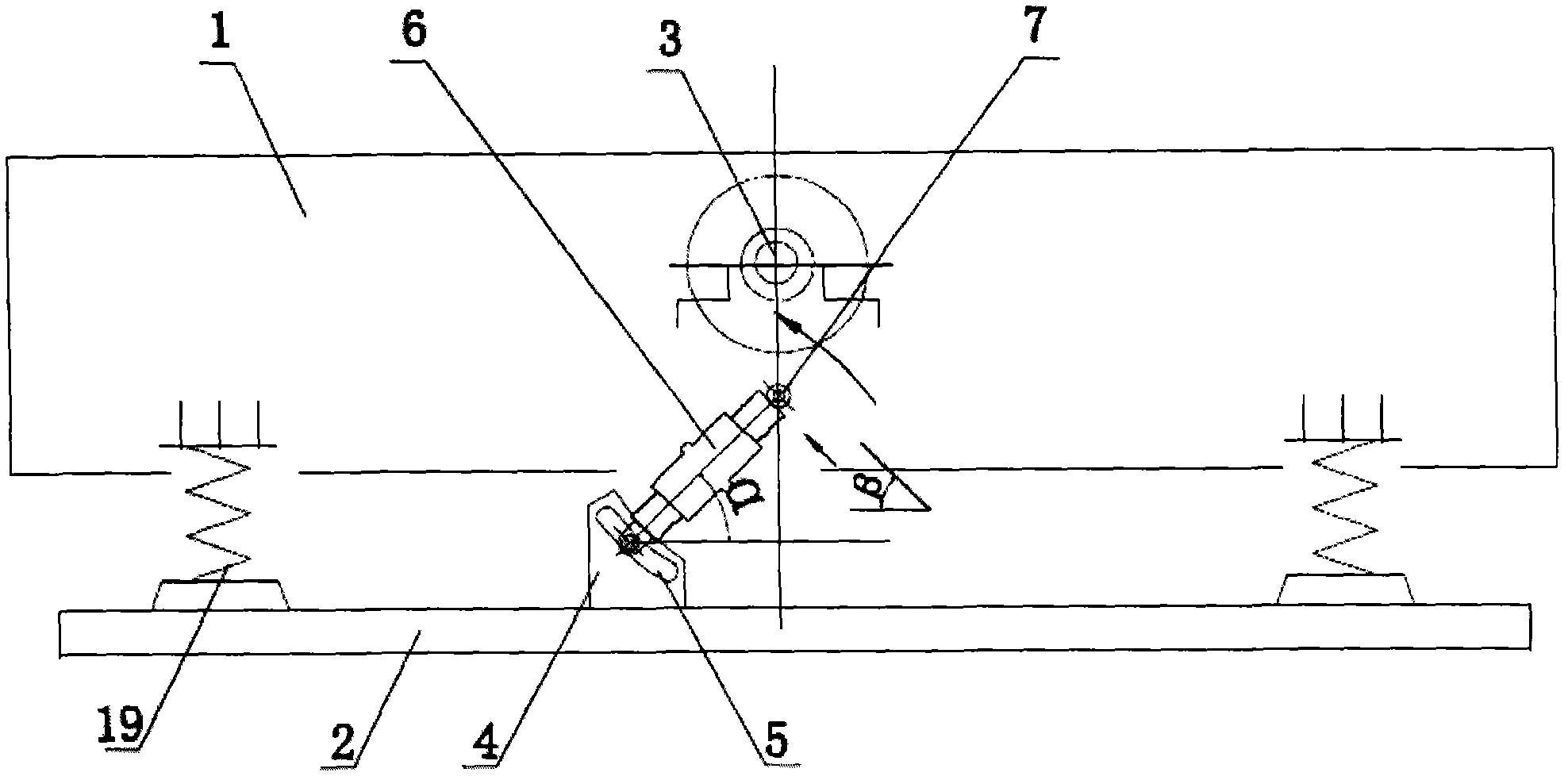
[0048] Embodiment 2: as figure 2 and image 3 As shown, a single-axis variable trajectory vibrator includes a vibration box 1, a base 2 and an excitation shaft 3. The vibration axis 3 is arranged on the vibration box 1, and the vibration box 1 and the base 2 Buffer springs 19 are arranged on the four corners.

[0049] Between the vibrating box 1 and the base 2 there is also an obliquely arranged rail-fixing rod 7 , which is a pair of rail-fixing rods 7 arranged symmetrically on both sides of the vibrating box 1 .

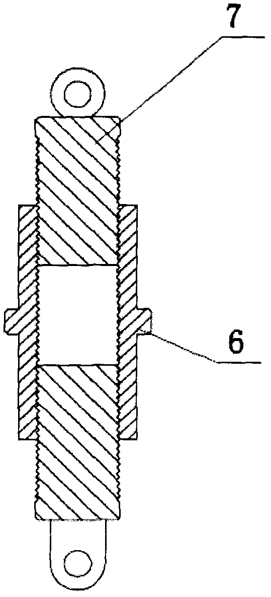
[0050] The rail-fixing rod 7 is the screw mandrel with the opposite thread direction of two sections separated, and the two-section rail-fixing rod 7 is connected together by the screw sleeve 6;

[0051] The hinge shaft between the lower end of the track rod 7 and the base 2 is arranged in the arc slot 5 and locked by the adjusting nut; the arc slot 5 is arranged on the base 4, and the base 4 is arranged on the base 2.

[0052] The rail-fixing rod 7 is arranged ...

Embodiment 3

[0053] Embodiment 3: as Figure 4 As shown, the upper end of the rail fixing rod 7 is sheathed in the sliding sleeve 8, and the sliding sleeve 8 is hinged on the vibration box 1. The lower end of the track rod 7 is hinged on the base 2.

[0054] All the other are with embodiment 2.


PUM


Abstract

The invention discloses a variable-track single-axle excitation vibrator, which comprises a vibrating case, a base and an eccentric shaft. The vibrating case is arranged on the base, buffer springs are arranged between the vibrating case and the base, the eccentric shaft is arranged on the vibrating case, a track determination bar assembly arranged obliquely is arranged between the vibrating case and the base and perpendicular to the fixed axis of the eccentric shaft, and two ends of the track determination bar assembly are respectively hinged to the vibrating case and the base. The variable-track single-axle excitation vibrator has the advantages that circular motion track of the single-axle excitation vibrator is changed into the linear or elliptical motion track by the aid of the design of the track determination bar assembly so that excitation vibration effect and efficiency are improved.

Description

technical field [0001] The invention relates to the technical field of vibrating machinery, in particular to an exciter assembly used in vibrating screens and feeders in mining machinery, and more specifically to a single-axis variable trajectory exciter. Background technique [0002] So far, the mechanical exciters in the prior art are basically divided into three categories: circular, straight, and elliptical in terms of motion trajectory, and the exciter structures used are three types: uniaxial, biaxial, and triaxial. The single-axis vibrator realizes the circular motion trajectory, the double-axis vibrator realizes the linear motion trajectory, and the three-axis vibrator realizes the elliptical motion trajectory. Although there are many improvements and innovations, many inventions and utility model patents have been disclosed. For example, the patent No. 200920213889.6 is named "Single-axis circular vibration track exciter for mechanical vibrating screens", and the pa...

Claims


Application Information

Patent Timeline
Patent Type & Authority Applications(China)
IPC IPC(8): B06B1/12
Inventor 朱兴良
Owner YIWU BLACK AND WHITE MINING MACHINERY
Features
  • R&D
  • Intellectual Property
  • Life Sciences
  • Materials
  • Tech Scout
  • Unparalleled Data Quality
  • Higher Quality Content
  • 60% Fewer Hallucinations
Learn More