Supercharge Your Innovation With Domain-Expert AI Agents!

Detachable type electric wire connection mounting tool

A technology for installing tools and connecting wires. It is used in electrical connection sockets, overhead lines/cable equipment, etc. It can solve problems such as small interphase distances, cabinet doors cannot be closed, and poor contact, so as to reduce volume occupancy, effectively and quickly adjust. , the effect of reducing difficulty

Inactive Publication Date: 2016-12-07
JINAN LICHENG POWER SUPPLY CO OF STATE GRID SHANDONG ELECTRIC POWER CO +1
View PDF6 Cites 5 Cited by
  • Summary
  • Abstract
  • Description
  • Claims
  • Application Information

AI Technical Summary

Problems solved by technology

[0003] (1) The structure of the insulating operation rod and the clamp is fixed, and it will be limited by the space when it is hung. Cabinet door cannot be closed
[0004] (2) When hanging the grounding wire, due to reasons such as the angle and the technical design of the grounding wire, the contact position of the conductive end is not in full contact, which will cause poor contact or even false hanging, which has certain potential safety hazards
[0005] (3) The metal part of the commonly used grounding wire clamp is too large, and the phase-to-phase distance of the current low-voltage complete power distribution device is very small, and even the distance between adjacent busbars is very small. It may accidentally touch the live busbar and cause a short circuit
Moreover, according to the requirements of safety regulations, when installing the ground wire, the three phase wires and the neutral wire must be directly grounded, so that there are four insulated wires to form a complete set of ground wires, and the quality and size are relatively large when the operator carries it.

Method used


Image

  • Detachable type electric wire connection mounting tool
  • Detachable type electric wire connection mounting tool
  • Detachable type electric wire connection mounting tool

Examples


Embodiment Construction

[0036] The features and principles of the present invention will be described in detail below in conjunction with the accompanying drawings, and the examples given are only used to explain the present invention, not to limit the protection scope of the present invention.

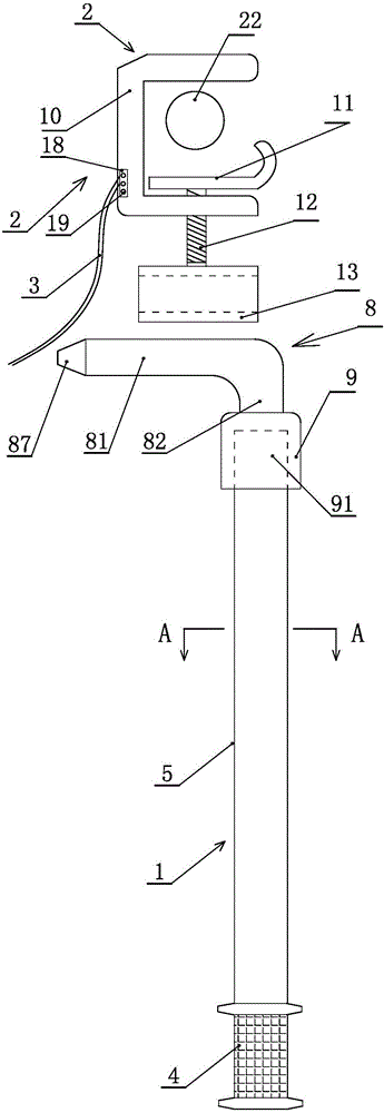
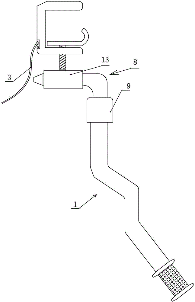
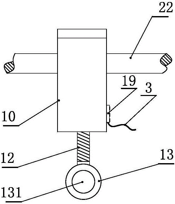
[0037] Such as figure 1 , figure 2 , image 3 Shown, this invention comprises operating lever part 1, wire clip part 2 and annealed copper wire 3 three major parts.

[0038] The clamp part 2 includes a fixed clamp body 10, a movable clamping part 11, a lead screw 12 and a rotating adjustment rod 13. The fixed clamp body is U-shaped, and a screw is installed at the bottom of the fixed clamp body. , the top of the lead screw is movably connected to a movable clamping part that cooperates with the fixed wire clamp body to realize clamping of the busbar, and the movable clamping part is also provided with a limiting part near the opening side of the fixed wire clamp body. The bottom end of the lead screw is ...


PUM


Abstract

The invention discloses a detachable type electric wire connection mounting tool. The detachable type electric wire connection mounting tool comprises an operating rod part, a wire clamp part and a soft copper wire, wherein an operating rod body comprises a metal strip and a rubber insulating layer which wraps the metal strip. The operating rod body is a rod body which can be bent at any angles, so that limitation by the space in hanging can be avoided, and operational difficulty in a narrow space is lowered; therefore, the condition that a cabinet door cannot be closed when a insulating rod cannot be bent and is exposed outside a switch cabinet can be prevented; in addition, the angle position of the insulating rod can be adjusted at will according to actual operating space and position requirements, thereby preventing from obstructing or from being obstructed by other objects, or a busbar and the like in the operation process; and by arrangement of a limiting part and a sawtooth-tooth-shaped part on the wire clamp, firm fixation between the wire clamp and a hung busbar is realized, so that loose hanging is prevented, the safety is improved, and potential safety hazards are avoided.

Description

technical field [0001] The invention relates to the technical field of electric power engineering, in particular to a detachable wiring installation tool. Background technique [0002] There are deficiencies in the installation of traditional low-voltage grounding wires: [0003] (1) The structure of the insulating operation rod and the clamp is fixed, and it will be limited by the space when it is hung. Cabinet door cannot be closed. [0004] (2) When the grounding wire is hung, due to reasons such as the angle and the technical design of the grounding wire, the contact position of the conductive end is not in full contact, which will cause poor contact or even false hanging, which has certain potential safety hazards. [0005] (3) The metal part of the commonly used grounding wire clamp is too large, and the phase-to-phase distance of the current low-voltage complete power distribution device is very small, and even the distance between adjacent busbars is very small. I...

Claims


Application Information

Patent Timeline
IPC IPC(8): H01R11/26H02G1/02
CPCH01R11/26H02G1/02
Inventor 刘勇张鑫王世强李希玉张阳孙驰贾友锋
Owner JINAN LICHENG POWER SUPPLY CO OF STATE GRID SHANDONG ELECTRIC POWER CO
Features
  • R&D
  • Intellectual Property
  • Life Sciences
  • Materials
  • Tech Scout
  • Unparalleled Data Quality
  • Higher Quality Content
  • 60% Fewer Hallucinations
Learn More